8.9.2 Application
GUID-3CA66549-3CB0-456C-B8FD-54F504792EB2 v2
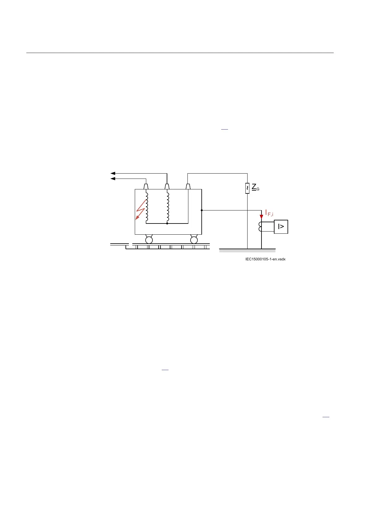
The transformer is placed on an insulated platform using the rails. The rails are cut
at each end and insulated with respect to ground by setting the holding-down bolts
in the concrete foundation without any contact to the reinforcement or by fixing the
rails on wooden ties.
The tank is grounded at a certain location by a conductor where a CT measures the
tank to ground current as shown in Figure 63.
The transformer tank protection function measures the current in the tank earth
conductor and give an instantaneous trip signal in case of an insulation break down
between a winding or terminal and the tank.
IEC15000105-1-en.vsdx
~
Z
G
I>
I
F,i
IEC15000105 V1 EN-US
Figure 63: Transformer tank and grounding arrangement
Transformer tank protection function is used to sense the tank leakage current and
operates if the current is above the set level.
In the case of grounded neutral systems, protection can be provided by insulating
the transformer tank from ground apart from a connection to ground through a CT
whose secondary energizes an overcurrent relay. Such an arrangement gives
sensitive protection for arc-overs to the tank or to the core, but it will not respond
to turn faults or to faults in the leads to the transformer.
The protection scheme should not initiate a trip in case of an external phase to
ground fault. Figure
64 illustrates the different elements that are involved in that
case.
The neutral displacement voltage that appears in case of an external phase to
ground fault is the source voltage for current flowing through the protection circuit.
The amount of this current is proportional to the ratio given by the ground contact
resistance R
G,C
to the leakage resistance R
G,I
of the tank as explained in Figure 64.
Section 8 1MRK 506 375-UEN A
Current protection
192 Railway application RER670 2.2 IEC
Application manual