IEC15000106-1-en.vsdx
~
Z
G
I>
I
F,e
R
G,I
R
G,c
V
NG
I
NG
IEC15000106 V1 EN-US
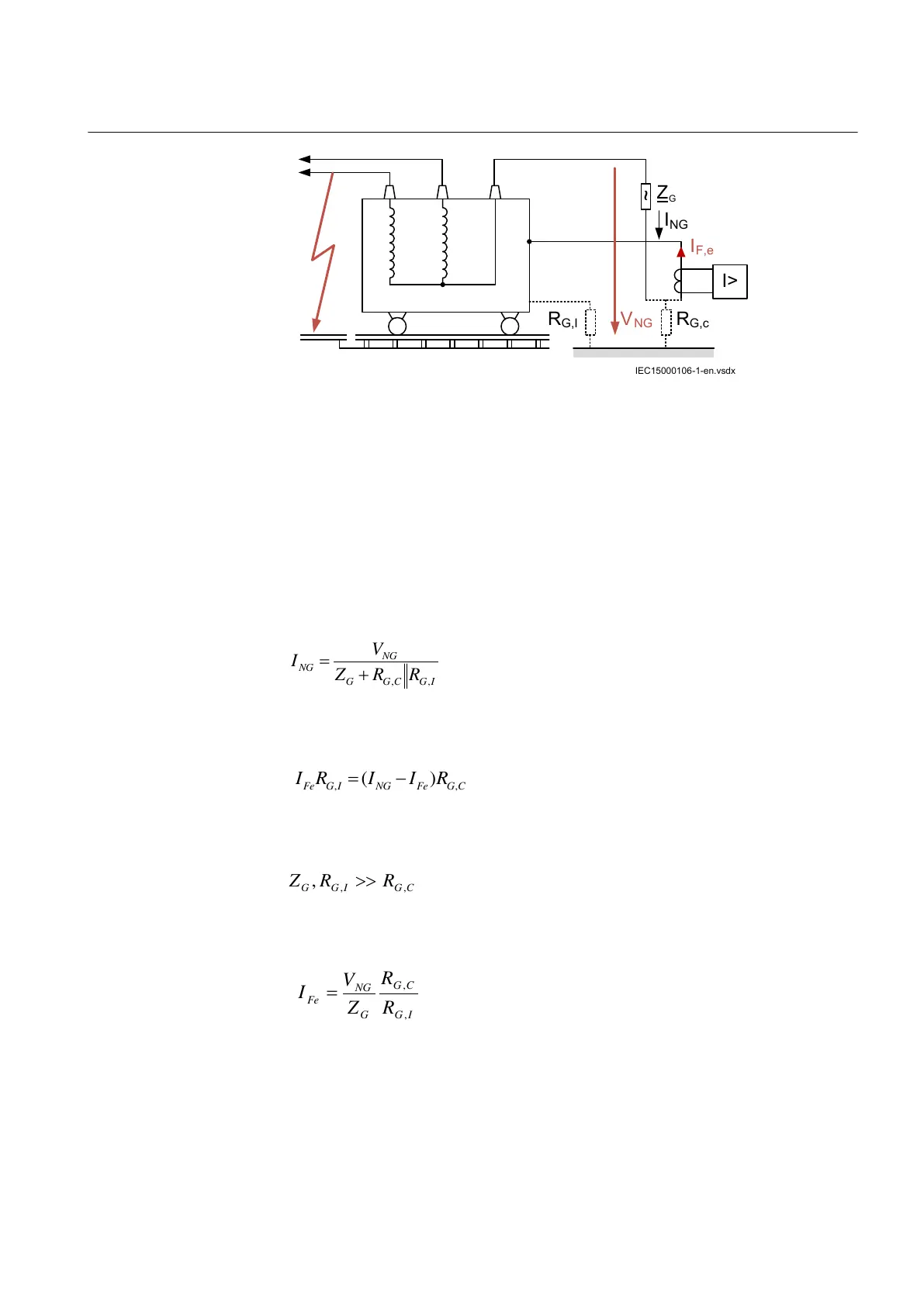
Figure 64: Behaviour of ground fault protection during an external fault
where:
R
G,I
Leakage resistance of the tank
R
G,C
Ground contact resistance
Z
G
Neutral grounding impedance
I
NG
is described as:
IECEQUATION051 V2 EN-US (Equation 58)
I
Fe
R
G,I
is described as:
IECEQUATION052 V2 EN-US (Equation 59)
For
IECEQUATION053 V2 EN-US (Equation 60)
I
Fe
is described as:
IECEQUATION054 V2 EN-US (Equation 61)
The current flow in case of an external phase to ground fault should not operate the
tank protection. Therefore, start value is set above the absolute value of this
current. In other words, the ratio of ground contact resistance R
G,C
to leakage
1MRK 506 375-UEN A Section 8
Current protection
Railway application RER670 2.2 IEC 193
Application manual