BC12CLTR (sect.1)
DCCLTR (A1A2)
DCCLTR (B1B2)
>1
&
BC12CLTR (sect.2)
&
VPBC12TR (sect.1)
VPDCTR (A1A2)
VPDCTR (B1B2)
VPBC12TR (sect.2)
>1
&
BC17OPTR (sect.1)
DCOPTR (A1A2)
BC17OPTR (sect.2)
>1
&
BC17CLTR (sect.1)
DCCLTR (A1A2)
BC17CLTR (sect.2)
&
VPBC17TR (sect.1)
VPDCTR (A1A2)
VPBC17TR (sect.2)
>1
&
>1
&
&
&
BC27OPTR (sect.1)
DCOPTR (B1B2)
BC27OPTR (sect.2)
BC27CLTR (sect.1)
DCCLTR (B1B2)
BC27CLTR (sect.2)
VPBC27TR (sect.1)
VPDCTR (B1B2)
VPBC27TR (sect.2)
EXDU_BC (sect.1)
EXDU_DC (A1A2)
EXDU_DC (B1B2)
EXDU_BC (sect.2)
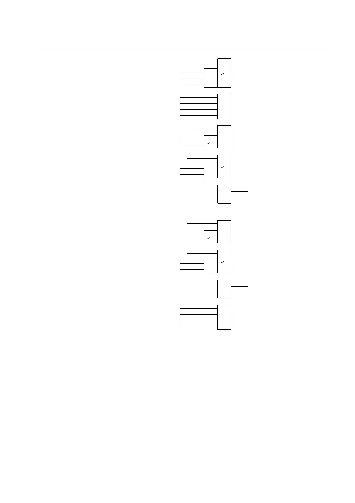
BC_12_CL
VP_BC_12
BC_17_OP
BC_17_CL
VP_BC_17
BC_27_OP
BC_27_CL
VP_BC_27
EXDU_BC
en04000480.vsd
IEC04000480 V1 EN-US
Figure 87: Signals to a line bay in section 1 from the bus-coupler bays in each
section
For a line bay in section 2, the same conditions as above are valid by changing
section 1 to section 2 and vice versa.
12.4.2.4 Configuration setting
M13560-108 v4
If there is no bypass busbar and therefore no QB7 disconnector, then the
interlocking for QB7 is not used. The states for QB7, QC71, BB7_D, BC_17,
1MRK 506 375-UEN A Section 12
Control
Railway application RER670 2.2 IEC 259
Application manual