to the TRM card and then connected to the fourth input of the respective
preprocessing SMAI function block in the ACT tool.
For installations where configuration shown in Figure 19 is used, all protection and
measurement functions inside IED can be used without any restrictions. Distance
protection will be able to measure and operate in all three measuring loops (i.e. L1-
Gnd, L2-Gnd and L1-L2).
In some AT
-catenary installation, second phase voltage UL2 (i.e. negative feeder
voltage) may not be available. In such case, refer to Section
Configuration example
3, for configuration of voltage analogue inputs. Practically, in such installations,
two-phase connection is used for currents and single-phase connection is used for
voltages. Note that in such special installations, distance or under-impedance
protection can only use L1-L2 measurement loop which will then effectively
measure impedance Z=UL1/(IL1-IL2). Directional earth fault protection and
residual overvoltage protection shall not be used in such installations. All other
backup protection and measurement functions can be used.
4.2.5.2 Configuration example 2
GUID-DB95191C-0313-436B-8800-1E3B021FD1A8 v1
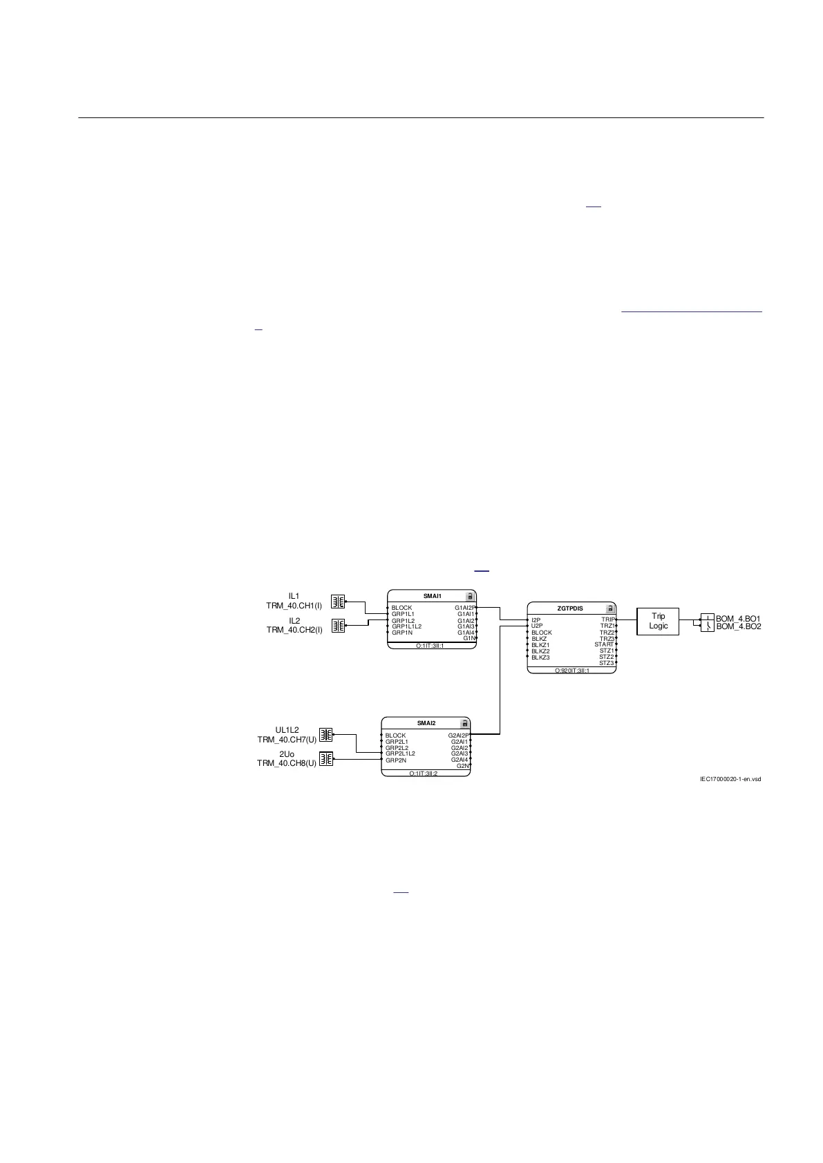
In HV two-phase railway supply systems grounded via Petersen Coil, sometimes
only one phase-to-phase voltage may be available instead of two single-phase to
ground voltages. An example on how to configure the IED analogue inputs for
such installation is shown in Figure 20.
IL1
TRM_40.CH1(I)
IL2
TRM_40.CH2(I)
UL1L2
TRM_40.CH7(U)
2Uo
TRM_40.CH8(U)
BOM_4.BO1
BOM_4.BO2
SMAI1
BLOCK
G1AI2P
O:1IT:3II:1
G1N
GRP1L1 G1AI1
GRP1L2 G1AI2
GRP1L1L2 G1AI3
GRP1N
G1AI4
SMAI2
O:1IT:3II:2
BLOCK
GRP2L1
GRP2L1L2
GRP2N
GRP2L2
G2AI2P
G2N
G2AI1
G2AI2
G2AI3
G2AI4
I2P
U2P
BLOCK
BLKZ
BLKZ1
BLKZ2
BLKZ3
TRIP
TRZ1
TRZ2
TRZ3
START
STZ1
STZ2
STZ3
O:920IT:3II:1
ZGTPDIS
Trip
Logic
IEC17000020-1-en.vsd
IEC17000020 V1 EN-US
Figure 20: Configuration for two-phase power system when only phase-to-
phase voltage is available
In order to make the IED to work in such system, the following steps to be
performed (see Figure
20):
1MRK 506 375-UEN A Section 4
Analog inputs
Railway application RER670 2.2 IEC 61
Application manual