6.2.4.1 Application examples
GUID-BAC97BE4-C678-435E-ACEE-7C90BB276E58 v2
Five examples of railway power transformer connections are presented here. Other
transformer connections may also be protected using the single-phase T1PPDIF
function.
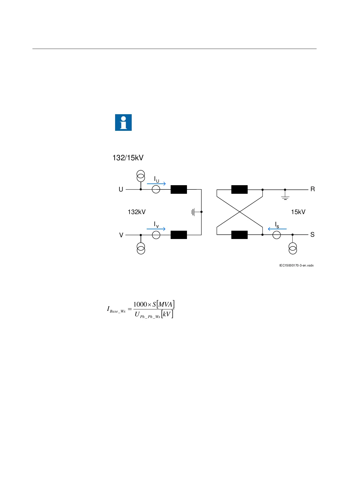
Transformer connection – example 1
GUID-0C1EBB70-8FBB-4AB9-8101-6E16B265FD7D v2
In all the following figures the phases are indicated as U and V on
the HV side and R and S on the L
V side of the transformer
.
Equivalent winding ends are U & R and V & S.
IEC15000170-3-en.vsdx
132/15kV
15kV132kV
I
U
v
I
U
I
s
S
V
R
IEC15000170 V3 EN-US
Figure 32: Transformer connection – example 1
Base current calculation:
kVU
MVAS
I
WxPhPh
WxBa se
__
_
1000
IECEQUATION058 V1 EN-US (Equation 6)
The HV currents I
V
and I
U
shall be connected as IL1 and IL2 currents, respectively,
for the winding 1 side towards the T1PPDIF function. The L
V current I
s
shall be
connected as IL1 current for the winding 2 side towards the T1PPDIF function.
Zero sequence current calculation on the HV side:
IECEQUATION200 V2 EN-US (Equation 7)
Removal of zero sequence current from the V phase:
1MRK 506 375-UEN A Section 6
Differential protection
Railway application RER670 2.2 IEC 85
Application manual