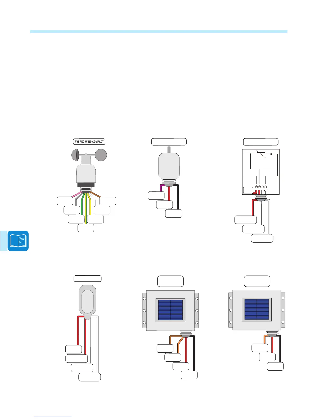
Connection diagrams for environmental sensors
Connection diagrams for the main sensors sold by ABB are shown below: Each of the environmental
sensors listed above, with the exception of the PVI-AEC-PYR-1300 Pyranometer should be
connected directly to the analog input of the Trio inverter. This data is then transmitted along with
the inverter’s data to the system’s data logger (VSN700 sold separately). For non-conventional
installations or additional information about the connections, please contact the technical support
department. Information on Weather Stations (VSN800) can be found at http://www.abb.com/
solarinverters (select Monitoring and Communication, then Environmental Monitoring).
A1/A2
(Wind speed)
A1/A2_RTN
+Vcc
-Vcc
Ground
+Vcc_Heat
(external)
-Vcc_Heat
(external)
RGETNI-0001T-CEA-IVP
+Vcc
A1/A2_RTN
-Vcc
A1/A2
HDA-001T-CEA-IVP
N.C.
RTD1PT100
(PT_RTN)
(PT_SENSE)
(PT_ALIM)
RTD2PT100
RTD3PT100
)ecnaidarrI(
)erutarepmet(
PVI-AEC-RAD-13-TC-T
PVI-AEC-IRR-T
A1
A2
+Vcc
A1/A2_RTN
-Vcc
PVI-AEC-RAD-13TC
A1/A2
A1/A2_RTN
+Vcc
-Vcc
PVI-AEC-IRR
RTD1PT1000
(PT_RTN)
(PT_SENSE)
(PT_ALIM)
RTD2PT1000
RTD3PT1000
PVI-AEC-T1000-BOX
N.C.

 Loading...


