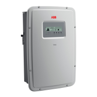
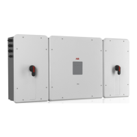
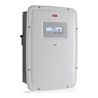
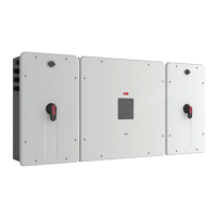
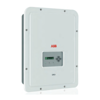
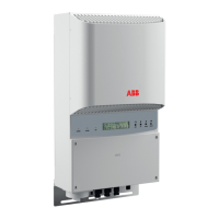
Wiring box components
There are four models of the wiring box available for either the 20.0 kW or 27.6 kW versions. Each model is
available with or without arc fault detection (AFD). The major differences between the wiring box layouts are
illustrated after the descriptions in the table below.
Ref. Description
01 Mounting bracket
02 Wiring box
03 Inverter
04 Coupling connector cover
05 Clamp screw
06 Optional lifting handles
07 Connector screws
08 Wiring box front cover
09 Communication board
10 Service cable and communications opening with plastic threaded plug, Trade size 1/2“
11 DC cable openings with plastic threaded plug *, Trade size 1”, 1 ½”
12 Solid copper jumper for paralleling inputs
13 DC terminal block (-S version)
14 DC disconnect switch handle
15 Class II DC surge protection (-S1, -S1A, -S1B versions)
16 AC cable opening with plastic threaded plug, Trade size 1”
17 AC terminal block
18 AC board (located behind 19 in –S1A and behind 20 in –S1B )
19 Class II AC surge protection (-S1A version)
20 Fused AC disconnect switch (-S1B version)
21 Anti-condensation valve (eliminates condensation buildup)
DO NOT REMOVE!
22 DC fuse holders (-S1, -S1A, -S1B versions)
23 Display
24 LED panel
25 Keypad
26 Heatsink
27 Equipment ground conductor (EGC) busbar (DC equipment grounding bar is common with the AC side; NO interconnecting
jumpers are required)
28 AC ground terminal
29 Arc fault detection (AFD) board
30 Positive input paralleling terminal blocks (use with non-AFCI versions only)
31 Negative input paralleling terminal blocks (use with non-AFCI versions only)
32 Bottom locking tab for securing mounting bracket to wall; can also be used as exterior grounding electrode conductor (GEC)
connection
33 Hole on wiring box cover and wiring box chassis used to insert a padlock
* If a 2” conduit is needed for DC cable, the DC cable entries can be punched to accommodate these using a knockout hole punch in
location of existing knockouts.

 Loading...


