a04
The actual value of these parameters
for marketed sensors are shown in the
appendix, section 7, and must have values
associated with the specic sensor loaded
by accessing the relevant menu. See
Operations, section 4, for setup of the
analog inputs.
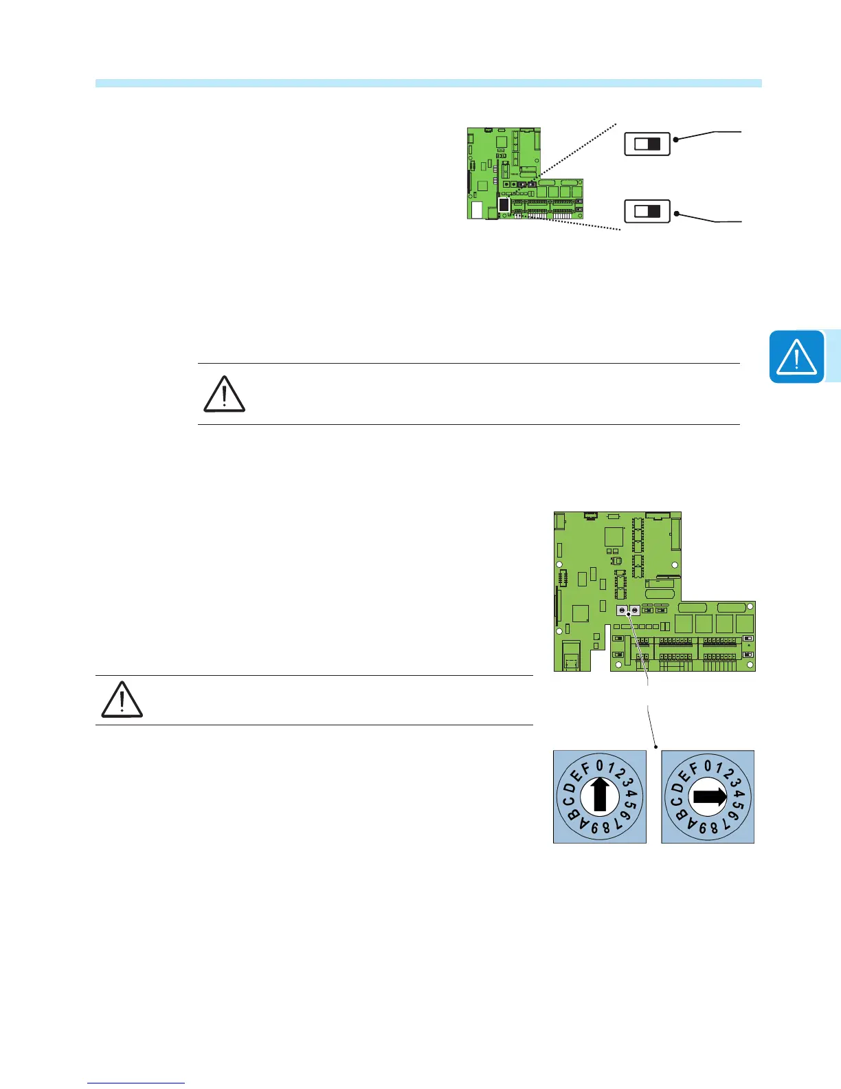
For each analog sensor, AN1 and AN2, it is also necessary to set the switch, a03 or a04, to select
whether the reading is in Volts or mA.
Connection diagrams for the main sensors marketed by ABB can be found in the Appendix,
section 7.
Each sensor model has precise conguration values that must be set accurately.
The power supply to the sensors must be installed outside the inverter, according
to the manufacturer’s specications.
Auxiliary +24 V service output a06
Included on connector a06, illustrated above, is a +24VDC service output. The maximum allowed
absorption by this auxiliary supply voltage is 300 mA.
Setting the country standard and language
The various grid parameters settings are dependent upon the country where
the inverter is installed. These settings are determined by the position of
switch a02 on the communication board. The language of the display menus
will be also be dened by the grid standard chosen.
Before turning the rotary switches, make sure the inverter is
switched off.
The TRIO is shipped with the predened settings for the North American
market, positions 0/4.
If it is necessary to reduce the maximum output power settings, the inverter
can be congured to position 1/A using the two rotary dials a02. See output
settings below. This setting utilizes the inverter active power management
function, and does not change the inverter power factor setting.
CARD
J10
PC
OFF
TERM.
120
OFF
J8
ON
PMU
S2
S4
ON
PC
PMU
J9
PMU -T/R
J6
CARD
COM
PMU +T/R
GND COM
+5V OUT
R ON/OFF
J4
PC
SH
J7
PC +T/R
PC -T/R
GND
RTD3
RTD3
24V
-WTACH
J5
+WTACH
PT100
RTD2
RTD2
PT1000
J3
J2
PMU
CR2032
A2
COM
A2
RTD1
RTD1
A1
A1
COM
S6
NORM
S3
S7
COUNTRY/LANG SEL
K1
S8
MEMORY
ALARM
NC
C
BT1
NO
S5
PAR IND SERV
A1
J16
J14
J11
AN2 AN1
V
mA
V
mA
S1
a02

 Loading...


