The PC port is used by ABB service personnel for rmware upgrade, troubleshoot-
ing and maintenance. When service interventions are required, user SCADA sys-
tems will need to be temporarily disconnected.
It is highly recommended that the Service/PC bus be interconnected between the
inverters and brought to a terminal strip at the data logger location. In this way,
future rmware upgrades can be applied to all inverters on the bus without having
to access the wiring box terminals of each one individually.
The PMU port can be used for SCADA systems and is the only choice for plant
control systems working on MODBUS protocol.
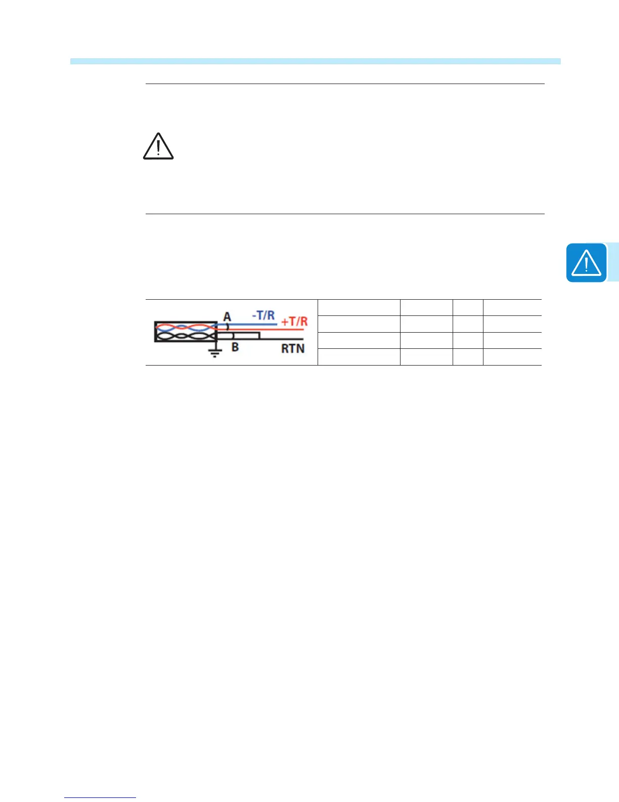
Use a cable designed for use with RS-485 communications such as Belden 3106A, which is a
data cable wire with one twisted pair for the +/-T/R signals, one ground conductor, and a shield
with drain wire (equivalent). The table below shows connections for a dual twisted pair shielded
cable.
Signal Symbol Pair Cable
Positive data +T/R A 1
Negative data -T/R A 2
Reference RTN B 1+2
Continuity of the shield in the RS-485 cable is important for low noise on the line; this is particularly
so for large plants with multiple inverters. For best results the shield must be tied to ground at only
one point on the line, typically at one end or the other.
The shield wiring must be continuous as it passes from one inverter to the next on a daisy chain,
but must not be tied to ground at these junctions.
The SH terminal is provided as a oating tie point for this purpose. It allows shields (drain wires)
from incoming and out-going daisy chain cables to be secured together but not grounded.
Daisy Chain units for connection to a monitoring system
The RS-485 terminal block connectors can be used to connect a single inverter or implement
a multi-unit wiring conguration called daisy chain. Note terminal block a07 has two rows of
contacts. The upper and lower rows are internally paralleled to allow daisy chain connections.
Using the appropriate cable designed for use with RS-485 communications, connect all the units
RS-485 lines in series according to the daisy chain cabling method ENTER-EXIT.
On the last inverter in a daisy chain, or on a single inverter, activate the termination resistance
of the communication line by moving switch a08 or a09 to ON position, being careful to set the
termination resistance switch of the serial line used (SERVICE/PC or MODBUS/PMU).

 Loading...


