Grid output connection (AC side)
• For suitable wire size (AWG), refer to NFPA National Electrical Code, Table 310.15(B)(16) (formerly
Table 310.16) for US.
• Use only Copper (Cu) wire rated for 75°C or 90°C (167°F or 194°F), solid or with type B or type C
stranding (19 strands maximum). For conductors with ner stranding, a suitable UL listed wire ferrule
must be used.
• Phase conductors must be sized based on ampacity requirements of the NEC or other applicable
prevailing code, but no smaller than 8 AWG Cu.
• The (Cu) neutral conductor is used only for voltage sensing within the inverter and may be sized equal
to or greater than the EGC conductor per NEC705.95(B).
• To prevent electrocution hazards, all the connection operations must be carried out with the external
AC disconnect switch downstream of the inverter (grid side) open and locked out.
• Before connecting the inverter to the grid, the grid standard for the country of installation must be
properly set. Refer to instructions on page 49 to congure this setting.
Characteristics and sizing of the AC output conductors
The AC output conductors must be sized properly to meet applicable code requirements and to
minimize effects of line voltage drops that can:
• Affect the overall system efciency, as this harvested power is lost directly to heat.
• Cause nuisance tripping (disconnection) of the inverter.
Wiring impedance that is too high can cause an increase in the AC voltage seen at the inverter
terminals, and in compliance with UL1741 and IEEE1547, could cause the inverter to disconnect
from the grid under otherwise normal grid operating conditions. IEEE1547 default settings
mandate the inverter operate normally if its terminal voltage is in the range of [+10%/-12%] of the
VNOM setting of the inverter.
To limit these issues the system designer must consider the worst case grid voltage conditions
and length of wiring runs between the inverter to the point of common connection, and size wiring
appropriately. For North America, based on ANSI B values, the worst case voltage range is +/-
6% of VNOM and line voltage drop in this case should be limited to less than 3% of VNOM. If
range is expected to be greater, then voltage drop must be decreased accordingly.
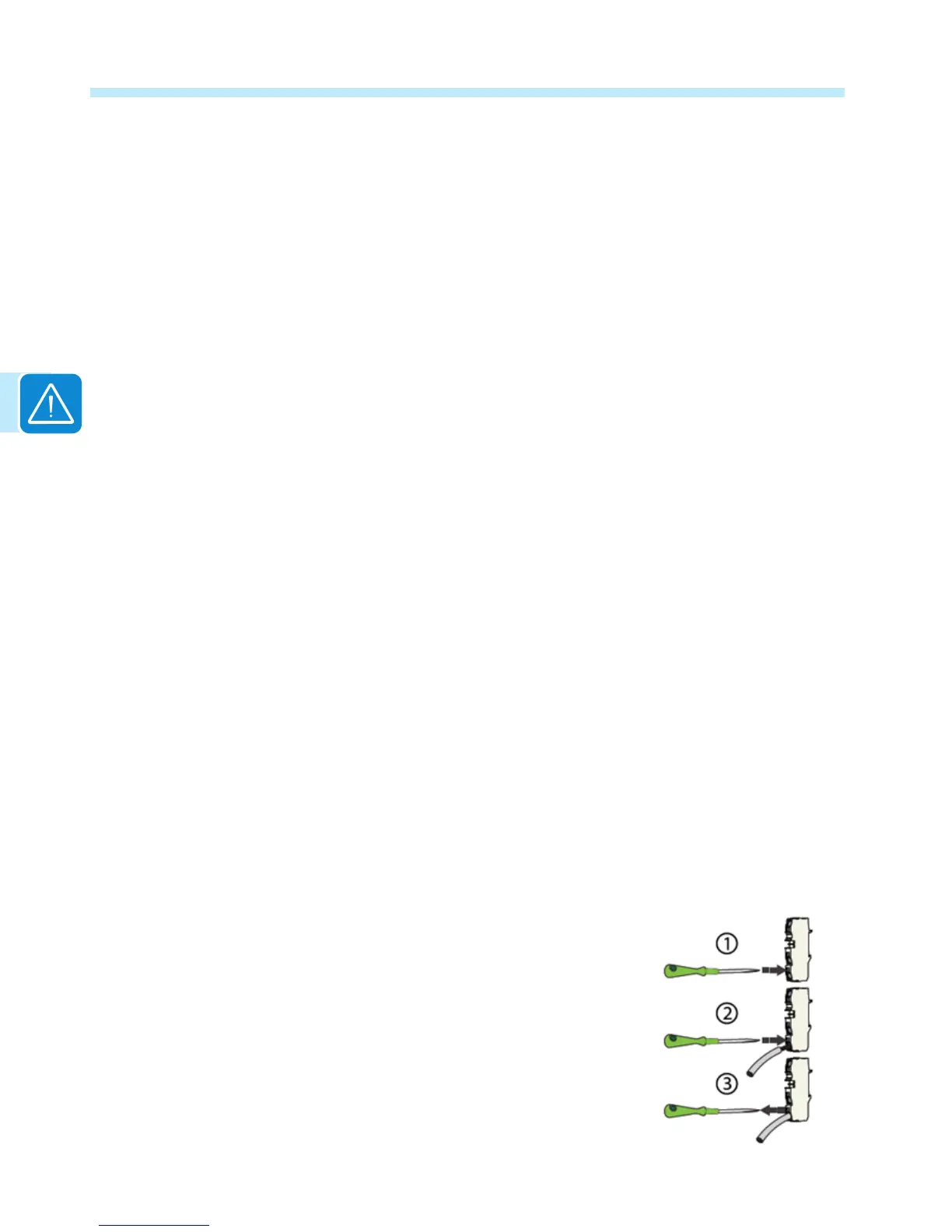
Wire installation
The TRIO Inverter has pressure type terminal blocks for
connection of the AC conductors. To connect wiring to these
blocks use the following procedure:
Strip ½” of insulation from the end of the conductor to be
terminated. Use a small (~1/4”wide) at blade screwdriver to
open the pressure contact:
• Insert the screwdriver in the rectangular tool slot.

 Loading...


