Connection of DC inputs -S1, –S1A, and -S1B models
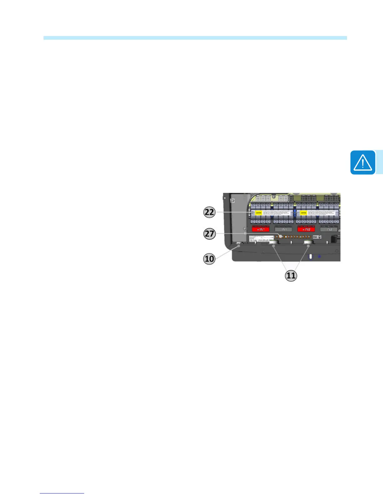
Remove the threaded plastic plug and nut from the DC cable opening 11 and insert the
appropriate conduit tting. Tighten to the chassis to ensure NEMA 4X compliance.
After reading the two CAUTION labels in place on the DC fuse blocks 22, remove them and then
open all fuse holders before connecting the PV strings.
Connect conductors to the correct input channel (if using the parallel conguration, either input
channel is acceptable).
The acceptable wire size range is from 12 AWG to 6 AWG, copper conductors only; refer to
local code for appropriate wire size. Fuse holders have screw terminals and the torque depends
on wire size. For wire sizes 10 AWG and larger, tighten to 30 in-lbs (3.4 Nm) torque.
Test each string for polarity and
voltage using a voltmeter (rated
2000V min.). After conrming
correct polarity and voltage on all
strings, close all fuse holders.
Connect any Equipment Grounding
conductors in the raceway to the
EGC busbar 27. The DC equipment
grounding bar is common with the
AC side and no other interconnecting
jumpers or the like are required.
String protection -S1, -S1A, and –S1B models
The -S1, -S1A and -S1B versions of the TRIO wiring box are provisioned with 30A rated UL
Listed/CSA certied fuse holders, supplied with 15A, 1000V DC rated fuses.
To determine the correct fuse value to use with a specic PV array, refer to the PV module
documentation and the National Electrical Code 690.8 and 690.9 or your local electrical code.

 Loading...


