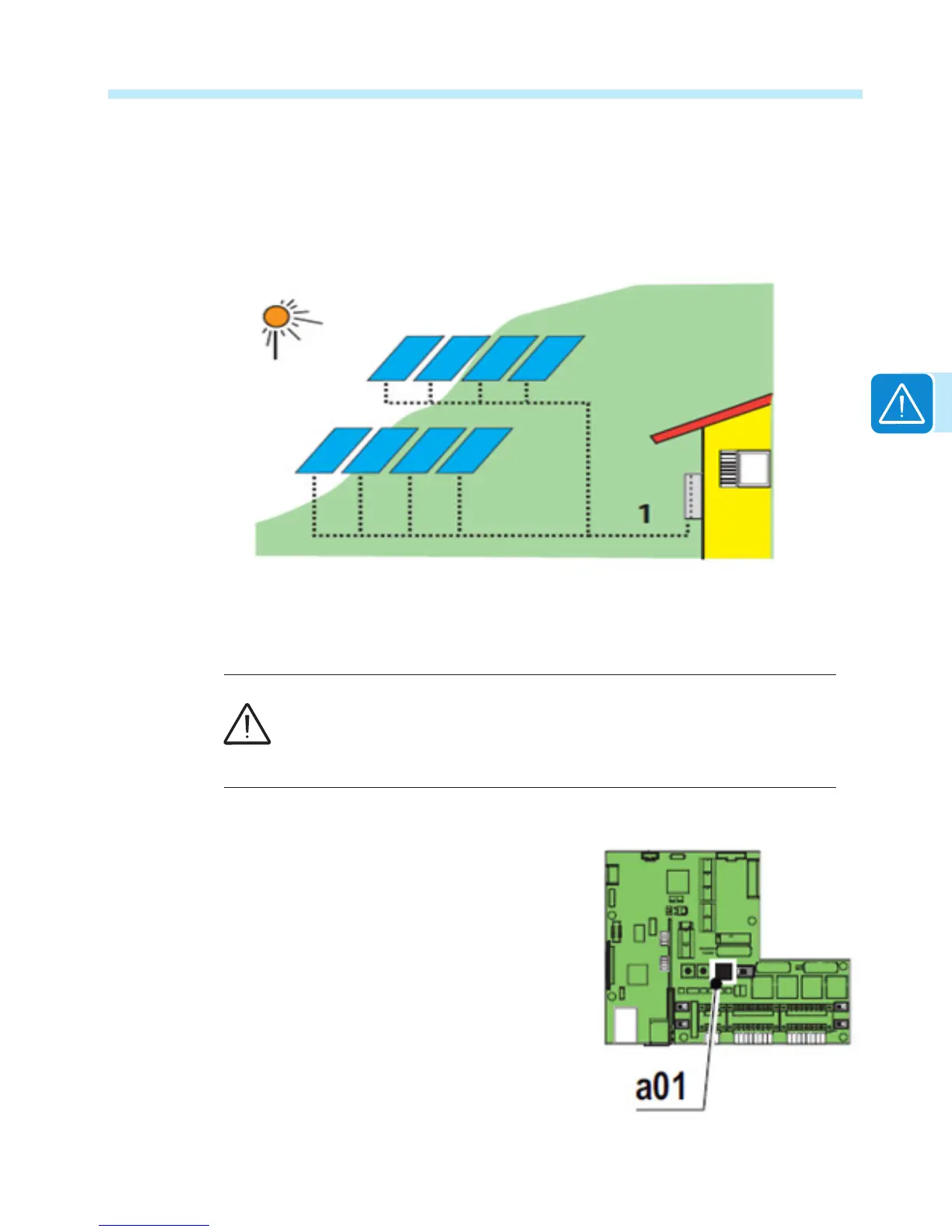
Single MPPT configuration – parallel mode (non-AFD models)
In the PARallel mode, the two channels are connected in parallel and strings of photovoltaic
modules having the same type and number of modules in series can be connected in parallel to
the single channel. All strings must be identical and oriented to the same sun azimuth.
Refer to MPPT conguration examples in the Appendix, section 7, for guidelines regarding the
choice of Parallel or Independent congurations. The TRIO Inverter is set in independent mode
at the factory by default. The following sections describe how to connect the inverter in parallel
mode.
In order to operate in the PARallel mode from a common array, it is necessary
to electrically connect the input channels in parallel using the jumpers provided
with this inverter. PARallel mode is only available on non-AFD models.
In addition, the input mode switch a01 located on the communication card 09
must also be set to the parallel mode as described below.
Setting the input mode switch a01
The input mode switch a01 located on the communication
card 09 is used to select the input conguration.
The TRIO is shipped from the factory with the input mode
switch in the IND (independent) conguration by default.
The a01 switch will be in the right most position.
To change the inverter input mode to the parallel
conguration, move switch a01 to the left-most position
to select PAR (parallel) mode.
Use the instructions on the next page to electrically
connect the input channels in parallel.

 Loading...


