Connections to the communication card
Remove the threaded plastic plugs from the service cable opening 10 and replace with the
appropriate conduit connector as noted below. Whether these cables need to be protected by
conduit depends on the applicable wiring code.
If no conduit is used, the cables should be brought into the wiring box via a 1/2” box connector
with rubber cable glands to maintain NEMA 4X rating.
If conduit is used, run the appropriate raceway and terminate it to the wiring box chassis using
a conduit connector that matches the raceway. The conduit must be terminated at one of the
two ½” openings 10. The sensor cables are connected on the communication card 09 using the
mating connectors supplied in the hardware bag shipped with the inverter.
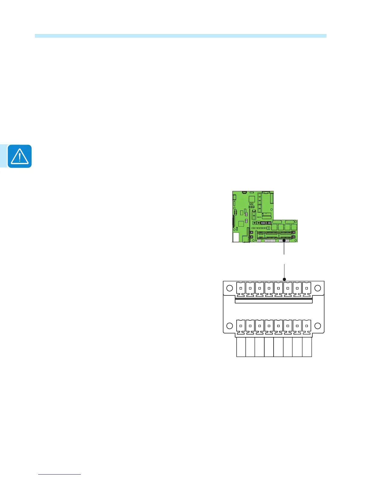
Serial communication a07 (RS-485)
There are two RS-485 communication lines on the
inverter. Each are accessed from terminal block a07.
Connect either communication port using terminal
block a07 (+T/R, -T/R and GND).
1) SERVICE/PC - dedicated line using AURORA
Protocol for the connection of ABB monitoring and
service equipment. PC port works only on AURORA
Protocol. Baud rate is xed at 19200 bit/s.
2) MODBUS/PMU - dedicated line for MODBUS RTU
communications. PMU port works on both MODBUS
and AURORA Protocol; MODBUS is the default. In
order to use AURORA Protocol on this port, it must be
set manually from the inverter display, unit by unit.
Baud rate can be chosen among the following list of
values: 2400 4800 9600 19200 38400 57600 115200.
Default value is 9600 bit/s. In order to change the
default value, it must be set manually from the display,
unit by unit.
If AURORA Protocol is set on this port it will work with a xed baud rate of 19200 bit/s. See the
Display Settings Menu in Operations, section 4, for instructions to change the PMU RS-485
protocol and/or baud rate.
a07
CARD
COM
CARD
PMU -T/R
PMU +T/R
GND COM
+5V OUT
R ON/OFF
J4
SH
PC +T/R
PC -T/R

 Loading...


