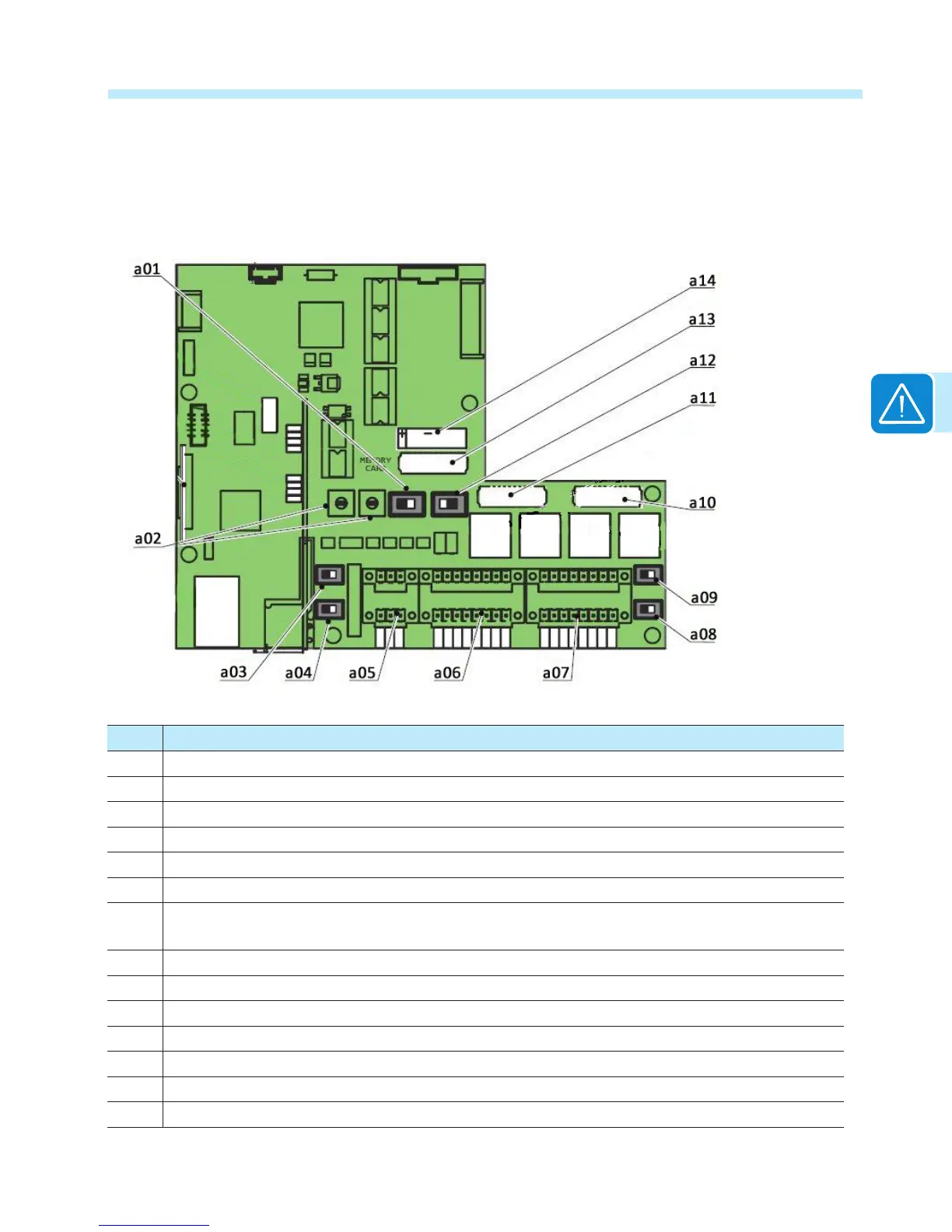
Labeled illustration of communication card 09
A removable plastic cover prevents access to the section of the wiring box where the communication card resides.
In order to access this area, remove the four screws in place and remove the cover.
Ref. Description
a01 Input mode switch for setting PARallel or INDdependent input modes
a02 Rotary switches for setting the country and the language of the display
a03 Switch for setting analog sensor 1 to Volts or mA
a04 Switch for setting analog sensor 2 to Volts or mA
a05 Connection to the multi-function relay
a06 Connection of environmental sensors: AN1, AN2, PT100, PT1000 and auxiliary 24V service output
a07 Connection for the RS-485 PC line (SERVICE), RS-485 PMU line (MODBUS), auxiliary 5V output
and remote ON/OFF
a08 Switch for setting the termination resistance of the RS-485 PMU line (MODBUS)
a09 Switch for setting the termination resistance of the RS-485 PC line (SERVICE)
a10 RS-485 PC communication card housing (SERVICE)
a11 RS-485 PMU communication card housing (MODBUS)
a12 Switch not activated; for factory use only (default = left most position)
a13 Inverter data memory card housing
a14 CR2032 battery housing

 Loading...


