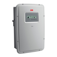
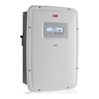
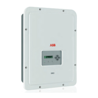
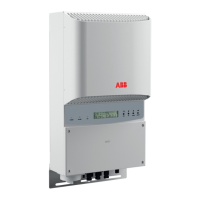
Display messages and error codes
The equipment indicates errors/warnings on the display only if the input voltage is higher than the Vdcmin voltage
(POWER LED ashing or on - see section 4, Operations). Next to each state of the inverter, (indicated through the
steady or intermittent lighting of the relevant LED), a message that identies the operation it is carrying out or the
detected fault/anomaly is also indicated in the two-line display. Messages identify the current status of the inverter
and do not relate to a fault.
When a (W) with a number after it appears in the display, it indicates a Warning Code and is usually cleared through
an orderly shutdown/reset or a self-corrective action performed by the inverter. Alarms or (E) codes identify a
possible equipment failure, fault, or incorrect inverter setting or conguration. Some of the (E) codes may require
technical support to assist in correcting a fault. Any and all attempts to correct or clear a fault must be performed
by qualied personnel. Typically, the (E) code can be cleared once the cause or fault is removed. Some of the
(E) codes may indicate a fatal error and require technical support for diagnostics and/or a product replacement.
When the red LED comes ON, try to reset the warning using the multi-function ESC button on the panel. If the
inverter reconnects to the grid, the fault was due to temporary phenomena.
WARNING! In the event of malfunction, it is extremely dangerous to try to eliminate the fault. Follow
the instructions given below or contact a specialized technician if you do not have the experience
and necessary qualications to work safely.
Table 5 - Display message errors and warnings
Display Message Causes Solution
Ground Fault
Red LED
The alarm is generated when
ground leakage current is
detected in the DC section of the
system.
The alarm is accompanied by
the lighting up of the red LED on
the front of the inverter.
If possible, measure the insulation resistance using a
megohmmeter positioned between the photovoltaic
eld (positive terminal short-circuited to the negative
pole) and ground.
If the measured value is less than 1 megohm, the
photovoltaic array must be checked by a technician/
installer to identify and eliminate the problem.
If the measured value is greater than 1 megohm and
the error warning continues to be present, contact
ABB technical support.
E001
Input OC
(Input Overcurrent)
The alarm appears when the
inverter input current exceeds
the set overcurrent threshold.
Check whether the conguration of the PV array
allows an input current that exceeds the maximum
threshold allowed by the inverter and that the
conguration of the (independent or parallel) inputs
is carried out correctly. If the conguration of the
PV array and the setting of the input channels are
suitable, contact ABB technical support.

 Loading...


