Connection to the PV field (DC side)
WARNING! The DC disconnect switch (14) disconnects ONLY the DC current from the photovoltaic
modules when the switch is open in the OFF position. It DOES NOT disconnect the AC connection
to the grid. To disconnect the inverter from the AC grid, an external, customer supplied AC switch
must be used.
To prevent electrocution hazards, all the connection operations must be carried out with the DC
disconnect switch (14) turned to the OFF position and locked out.
When connecting the DC conductors verify polarity prior to terminating. Conrm maximum system
voltage will never exceed 1000V per NEC requirements. Failure to perform these checks may cause
arcing and potential re.
• The electrical installation of the TRIO inverter must be performed in accordance with the electrical standards
prescribed by the local regulations and by the National Electric Code.
• For suitable wire size (AWG), refer to NFPA National Electrical Code, Table 310.15(B) (formerly Table 310.16)
for US.
• Use only Copper (Cu) wire rated for 75°C or 90°C (167°F or 194°F), solid or with type B or type C stranding (19
strands maximum). For conductors with ner stranding, a suitable UL listed wire ferrule must be used.
• All wiring connections are made inside the wiring box 02.
• If the inverter is to be mounted at a later time, ensure the coupling connector cover 04 is in place to protect the
connector on the wiring box until the inverter is to be mounted.
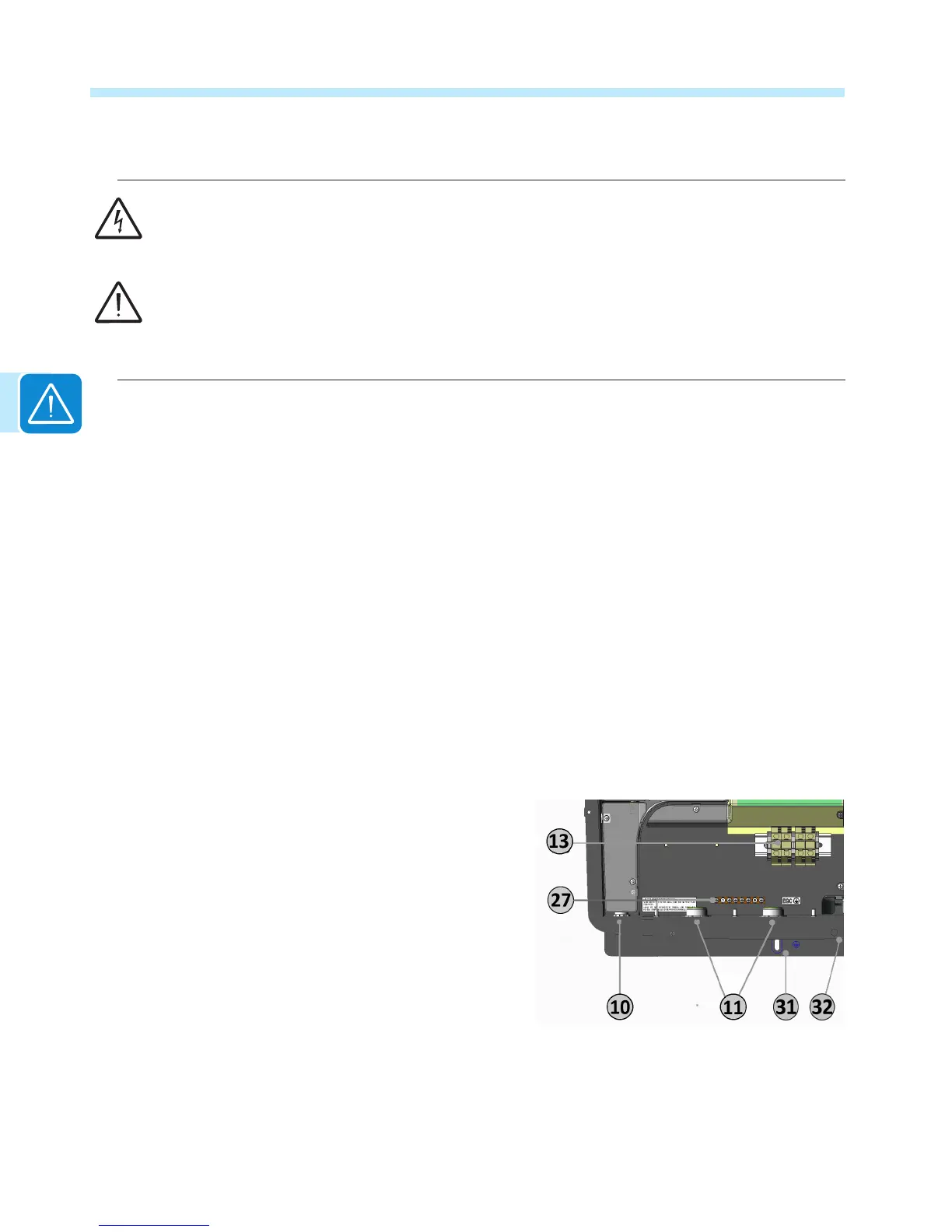
Connection of DC inputs -S model
Remove the threaded plastic plug and nut from the DC cable opening 11 and insert the appropriate
conduit tting. Tighten to the chassis to ensure NEMA 4X compliance.
Make appropriate conduit runs from array and pull the array conductors through the raceway to
the inverter.
The acceptable conductor cross-section ranges
from 12 AWG to 2 AWG, copper conductors only.
Tighten with at least 22 in-lbs (6Nm) torque.
Connect the conductors to the correct terminals
on the DC terminal block 13. Using a voltmeter
(rated 2000V min.) test each string for polarity
and voltage.
Verify that the DC voltage in the wiring box has
the correct polarity and is within the operational
range.
After conrming correct polarity and voltage on all strings, connect any Equipment Grounding
conductors in the raceway to the EGC busbar 27. The DC equipment grounding bar is common
with the AC side and no other interconnecting jumpers or the like are required.

 Loading...


