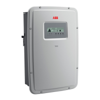
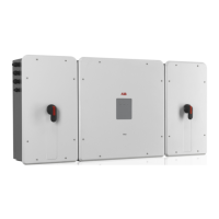
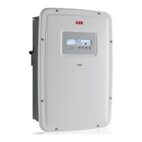
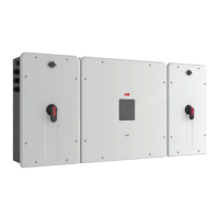
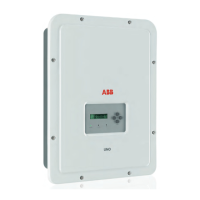
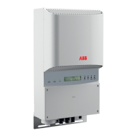
Topographic diagram of the equipment
The block diagram on the next page displays the inverter’s operational parts. The main blocks are the input boost
converters and the output inverter. Both the boost converters and the output inverter operate at high-switching
frequencies, resulting in a compact size and relatively light weight.
Each of the input converters is dedicated to a separate array with independent maximum power point tracking
(MPPT) control. This means that the two arrays can be installed with different positions and orientation. Each array
is controlled by an MPPT control circuit. The two trackers on non-AFD models can be congured in parallel, to
handle power and/or current levels higher than those a single tracker can handle.
This inverter was designed without an isolation transformer, which results in increased efciency and enables a
further increase in conversion efciency. The inverter is already equipped with all the necessary protective devices
for safe operation in compliance with regulations, even without an isolation transformer.
The inverter is controlled by two independent DSPs (Digital Signal Processors) and a central microprocessor. The
connection to the utility grid is therefore controlled by two independent computers, in full compliance with electrical
standards regarding system powering and safety.
The operating system performs the operation of communicating with the relevant components to carry out data
analysis. This guarantees optimal operation of the entire unit and high efciency in all insolation and load conditions,
always in full compliance with relevant directives, standards and provisions.

 Loading...


