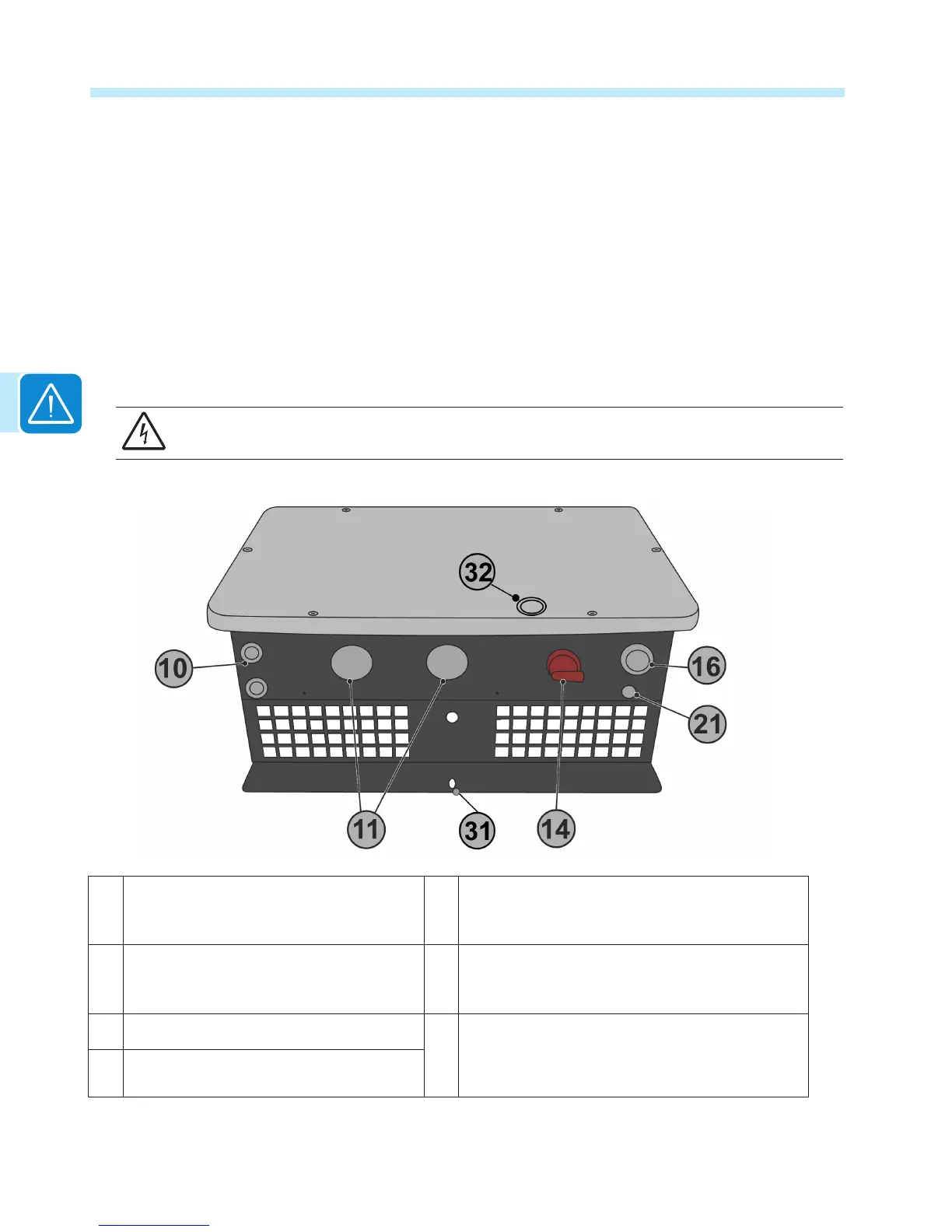
Conduit entries for all versions are located on the bottom of the wiring box along with the DC disconnect switch
handle 14. Conduit entries are illustrated below. The appropriate conduit connector must be used in order to
maintain required spacing between wiring groups and preserve the integrity of the NEMA 4X environmental rating.
• A silkscreen printed label on the wiring box front cover 08 illustrates the ON/OFF positioning of the disconnect
switch handle.
• In the OFF position (open and locked), the DC disconnect switch handle will be turned counter-clockwise in a
position parallel to the inverter mounting surface as illustrated below.
• In the ON position, the DC disconnect switch handle must be pushed in and turned clockwise to a position
perpendicular to the inverter mounting surface.
• The cover is only removable with the DC disconnect switch handle set to the OFF position.
• A padlock can be inserted in the slot on the switch handle when in the OFF position to prevent the disconnect
from being turned to the ON position.
WARNING! The DC switch (14) disconnects the photovoltaic array current from the inverter when
the switch is in OFF position. It DOES NOT disconnect the AC from the grid.
10 Service and communications cable open-
ing with plastic threaded plug, Trade size
1/2“
21 Anti-condensation valve (eliminates
condensation buildup) DO NOT REMOVE!
11 DC cable openings with plastic threaded
plug, Trade size 1”, 1 ½”
31 Bottom locking tab for securing mounting bracket
to inverter and wiring box, can also be used as
exterior grounding electrode terminal if required.
14 DC disconnect switch handle.
32 Hole on wiring box cover and wiring box chassis
used to insert a padlock,if required.
16 AC cable opening with plastic threaded
plug, Trade size 1”

 Loading...


