2. Once the inverter is powered, icon b11
comes on to indicate that the voltage from the
photovoltaic array has reached the Vstart threshold
(voltage necessary for connecting the inverter to the
grid).
For input voltages lower than Vstart, the icon b11
remains off, the Waiting Sun message is shown on
the display and the voltage and current values are
present (icons b12 and b13).
3. For -A models only, as soon as Waiting
Sun conditions are met, the inverter display shows
the AFD board self-test running. The results are
displayed in the two-line graphic display area b7.
If a problem on the AFD board is detected, the self-test will result in an error.
Refer to Troubleshooting, section 5, to clear the error and possible solutions.
4. If there are no irregularities after checking the grid voltage and frequency parameters, the
grid connection sequence starts. Once all the checks are nished, and all grid parameters are
observed, icon b19 comes on.
During these checks, icon b19 is ashing. This check can take several minutes depending on grid
conditions and grid standard settings.
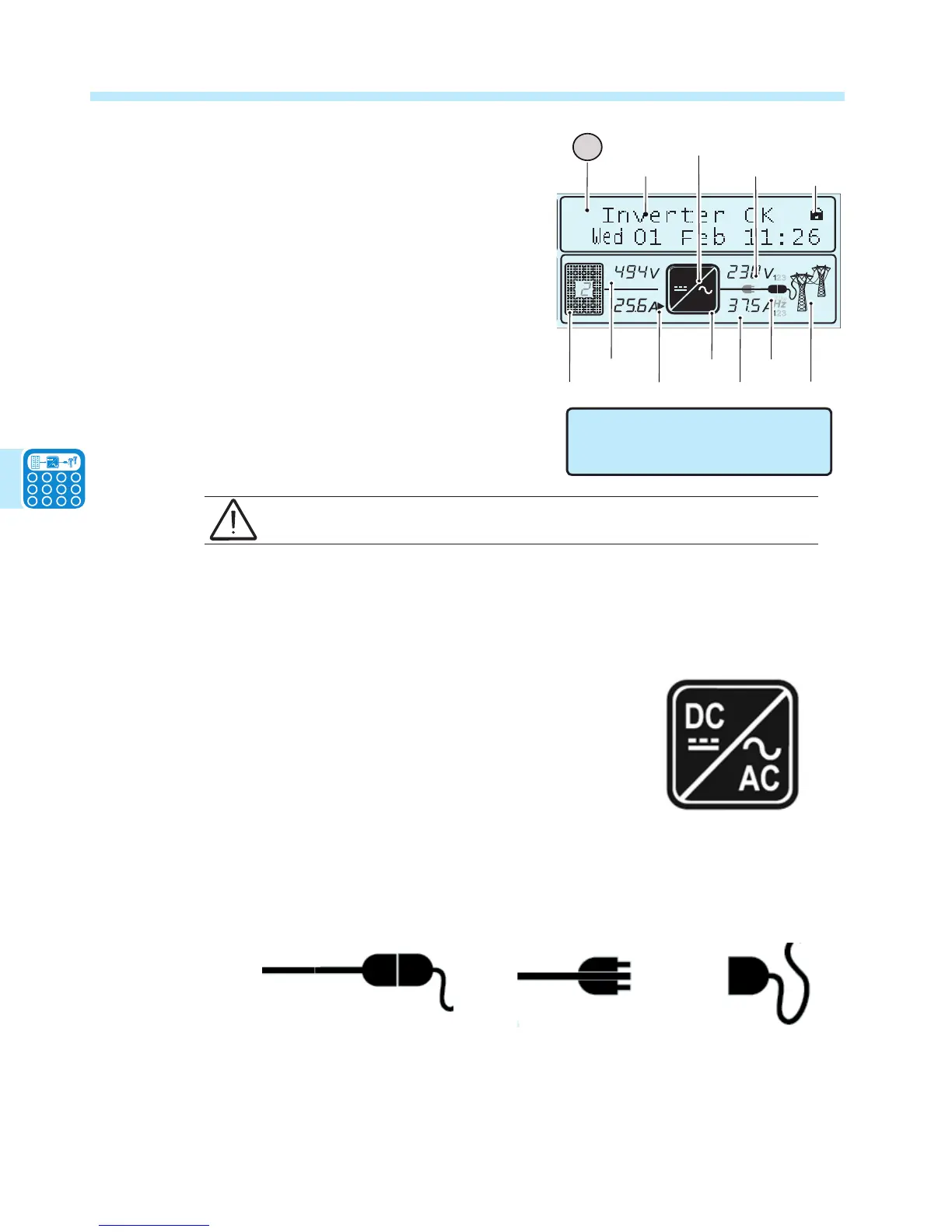
5. At this point icon b14 ashes to indicate the start-up
phase. This icon will remain permanently switched ON when
the DC-DC is operating at steady state.
At the same time as icon b14 comes on (steady), icon b15 will
come on to indicate that the inverter circuit has begun working (DC- AC).
6. The grid connection will start immediately. During this phase the icon b18 will be displayed
in steps until the connection of the inverter is complete. After the inverter is connected, icon b18
will stay plugged in as shown below.
Icon b18 – inverter connected to network
(plugged in)
Icon b18 - inverter not connected to network
(unplugged)
Once the connection sequence is complete, the inverter starts to operate and indicates correct
operation by the steady green LED light on the panel. This means there is sufcient sunlight to
feed power into the grid.
DC
AC
23

 Loading...


