MC96F6432
June 22, 2018 Ver. 2.9 123
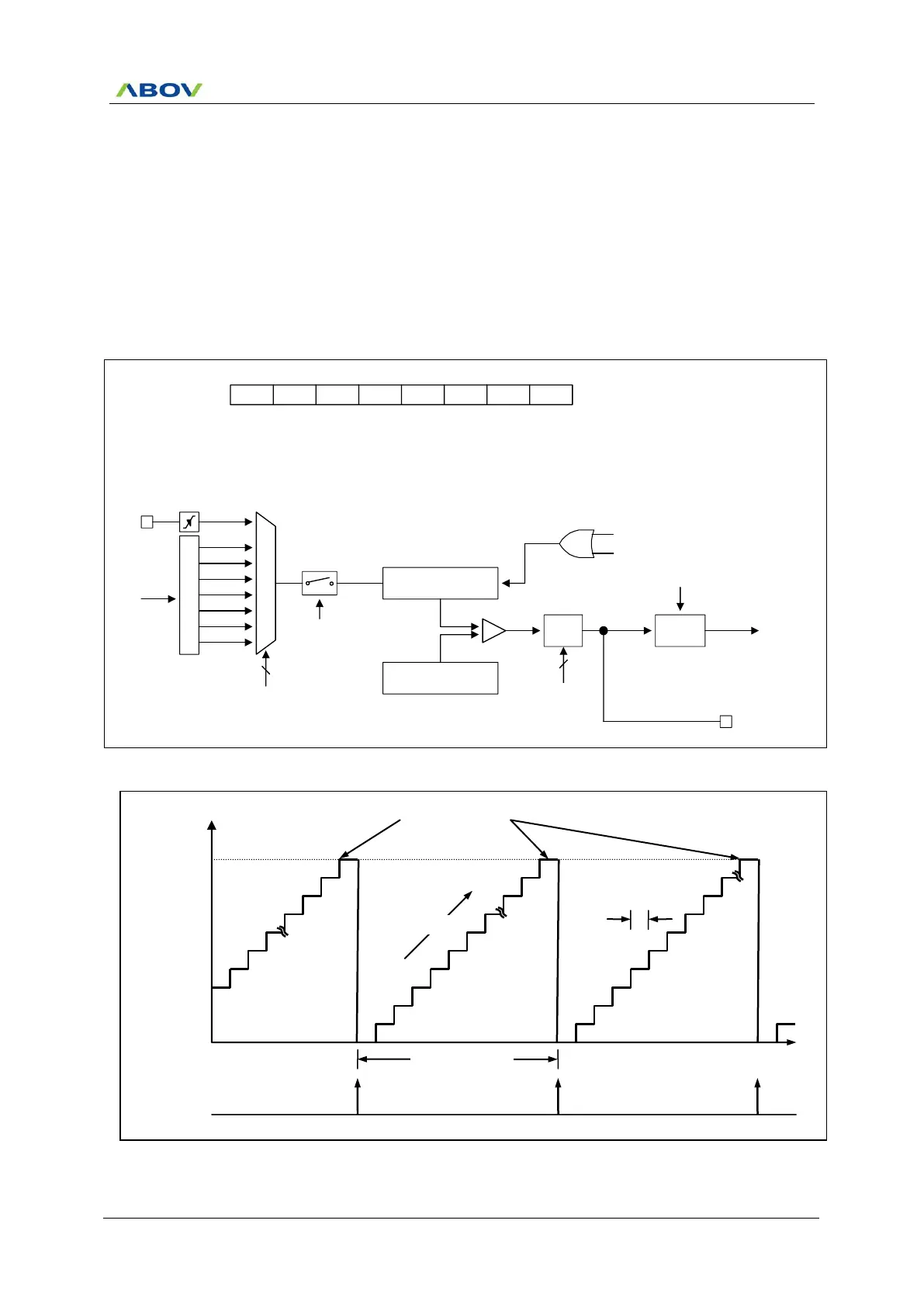
11.5.2 8-Bit Timer/Counter Mode
The 8-bit timer/counter mode is selected by control register as shown in Figure 11.6.
The 8-bit timer have counter and data register. The counter register is increased by internal or external clock
input. Timer 0 can use the input clock with one of 2, 4, 8, 32, 128, 512 and 2048 prescaler division rates
(T0CK[2:0]). When the value of T0CNT and T0DR is identical in timer 0, a match signal is generated and the
interrupt of Timer 0 occurs. T0CNT value is automatically cleared by match signal. It can be also cleared by
software (T0CC).
The external clock (EC0) counts up the timer at the rising edge. If the EC0 is selected as a clock source by
T0CK[2:0], EC0 port should be set to the input port by P52IO bit.
P
r
e
s
c
a
l
e
r
fx
M
U
X
fx/2
T0CNT(8Bit)
EC0
fx/4
fx/8
fx/32
fx/128
fx/512
fx/2048
3
T0CK[2:0]
T0EN
8-bit Timer 0 Counter
T0DR(8Bit)
Comparator
T0IFR
T0O/PWM0O
8-bit Timer 0 Data Register
INT_ACK
Clear
Match signal
Clear
Match
MUX
T0MS[1:0]
2
To interrupt
block
T0EN - T0MS1 T0MS0 T0CK2 T0CK1 T0CK0 T0CCT0CR
1 - 0 0 x x x x
ADDRESS : B2H
INITIAL VALUE: 0000_0000B
T0CC
Figure 11.6 8-Bit Timer/Counter Mode for Timer 0
Figure 11.7 8-Bit Timer/Counter 0 Example
Timer 0
(T0IFR)
Interrupt
Interrupt Period
= P
CP
x (n+1)

 Loading...


