MC96F6432
124 June 22, 2018 Ver. 2.9
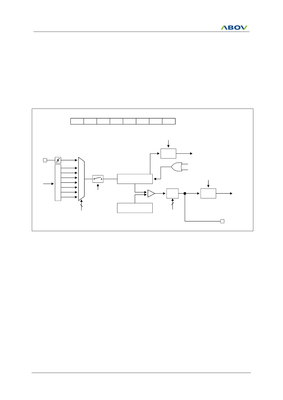
11.5.3 8-Bit PWM Mode
The timer 0 has a high speed PWM (Pulse Width Modulation) function. In PWM mode, T0O/PWM0O pin
outputs up to 8-bit resolution PWM output. This pin should be configured as a PWM output by setting the
T0O/PWM0O function by P5FSR[4:3] bits. In the 8-bit timer/counter mode, a match signal is generated when the
counter value is identical to the value of T0DR. When the value of T0CNT and T0DR is identical in timer 0, a
match signal is generated and the interrupt of timer 0 occurs. In PWM mode, the match signal does not clear the
counter. Instead, it runs continuously, overflowing at “FFH”, and then continues incrementing from “00H”. The
timer 0 overflow interrupt is generated whenever a counter overflow occurs. T0CNT value is cleared by software
(T0CC) bit.
P
r
e
s
c
a
l
e
r
fx
M
U
X
fx/2
T0CNT(8Bit)
EC0
fx/4
fx/8
fx/32
fx/128
fx/512
fx/2048
3
T0CK[2:0]
T0EN
8-bit Timer 0 Counter
T0DR(8Bit)
Comparator
T0IFR
T0O/PWM0O
8-bit Timer 0 Data Register
INT_ACK
Clear
Clear
Match
MUX
T0OVIFR
Clear
T0MS[1:0]
2
INT_ACK
To interrupt
block
To interrupt
block
T0EN - T0MS1 T0MS0 T0CK2 T0CK1 T0CK0 T0CCT0CR
1 - 0 1 x x x x
ADDRESS : B2H
INITIAL VALUE: 0000_0000B
Match signal
T0CC
Figure 11.8 8-Bit PWM Mode for Timer 0

 Loading...


