EasyManuals Logo

Abov MC96F6432 Series User Manual

Abov MC96F6432 Series
327 pages
To Next Page IconTo Next Page
To Previous Page IconTo Previous Page
Page #277 background imageLoading...
Page #277 background image
MC96F6432
June 22, 2018 Ver. 2.9 277
VSS
R’ R’ R’ R’
VLC0 VLC1 VLC2 VLC3
VLCD
(1/4 BIAS)
VSS
R’ R’
VLC0 VLC1 VLC2 VLC3
VLCD
(1/2 BIAS)
VSS
R’R’R’
VLC0 VLC1 VLC2 VLC3
VLCD
(1/3 BIAS)
LCTEN
DISP
Contrast
Controller
LCTEN
DISP
Contrast
Controller
LCTEN
DISP
Contrast
Controller
NOTES)
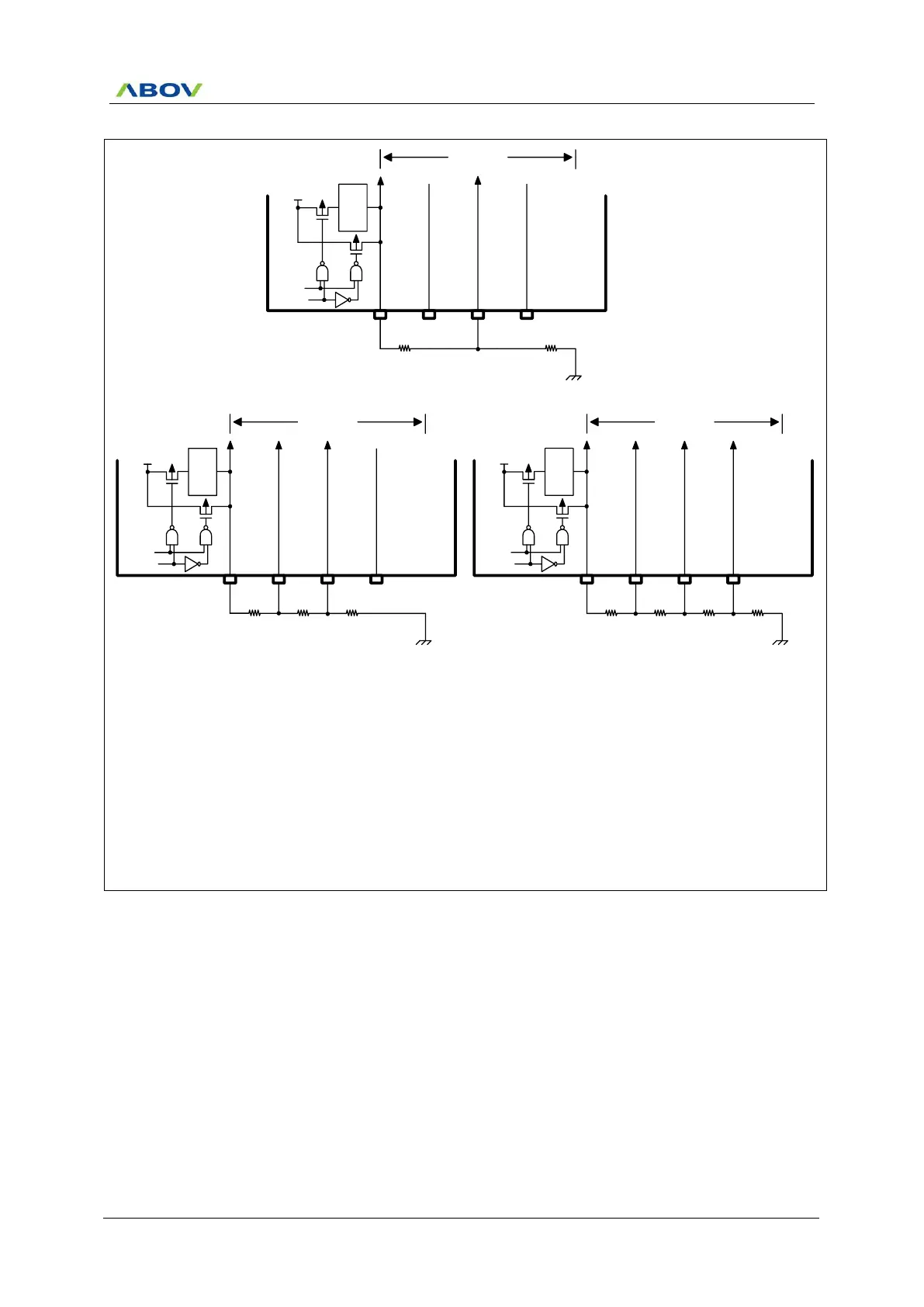
1. When the external resistor bias is selected, the internal resistors for bias are disconnected.
2. When the external resistor bias is selected, the dividing resistors should be connected like the above figure
and the needed bias pins should be selected as the LCD bias function pins (VLC0, VLC1, VLC2, and VLC3) by
P4FSR register.
- When it is 1/2 bias, the P43/VLC0 and P41/VLC2 pins should be selected as VLC0 and VLC2 functions.
The other pins can be used for normal I/O.
- When it is 1/3 bias, the P43/VLC0, P42/VLC1, and P41/VLC2 pins should be selected as VLC0, VLC1, and
VLC2 functions. Another pin can be used for normal I/O.
- When it is 1/4 bias, the P43/VLC0, P42/VLC1, P41/VLC2, and P40/VLC3 pins should be selected as VLC0,
VLC1, VLC2, and VLC3 functions
Figure 11.105 External Resistor Bias Connection

Table of Contents

Questions and Answers:

Question and Answer IconNeed help?

Do you have a question about the Abov MC96F6432 Series and is the answer not in the manual?

Abov MC96F6432 Series Specifications

General IconGeneral
BrandAbov
ModelMC96F6432 Series
CategoryMicrocontrollers
LanguageEnglish

Related product manuals