EasyManuals Logo

Abov MC96F6432 Series User Manual

Abov MC96F6432 Series
327 pages
To Next Page IconTo Next Page
To Previous Page IconTo Previous Page
Page #192 background imageLoading...
Page #192 background image
MC96F6432
192 June 22, 2018 Ver. 2.9
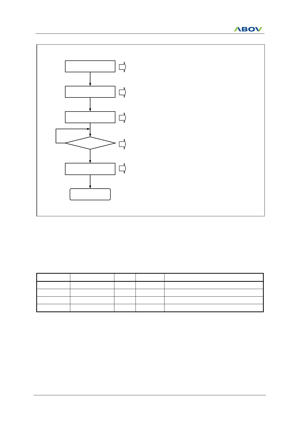
Figure 11.56 A/D Converter Operation Flow
11.11.5 Register Map
Table 11-18 ADC Register Map
Name
Address
Dir
Default
Description
ADCDRH
9FH
R
xxH
A/D Converter Data High Register
ADCDRL
9EH
R
xxH
A/D Converter Data Low Register
ADCCRH
9DH
R/W
00H
A/D Converter Control High Register
ADCCRL
9CH
R/W
00H
A/D Converter Control Low Register
11.11.6 ADC Register Description
The ADC register consists of A/D converter data high register (ADCDRH), A/D converter data low register
(ADCDRL), A/D converter control high register (ADCCRH) and A/D converter control low register (ADCCRL).
SET ADCCRH
SET ADCCRL
AFLAG = 1?
Converting START
READ ADCDRH/L
ADC END
Select ADC Clock and Data Align Bit.
ADC enable & Select AN Input Channel.
Start ADC Conversion.
If Conversion is completed, AFLAG is set 1 and ADC
interrupt is occurred.
After Conversion is completed, read ADCDRH and ADCDRL.
Y
N

Table of Contents

Questions and Answers:

Question and Answer IconNeed help?

Do you have a question about the Abov MC96F6432 Series and is the answer not in the manual?

Abov MC96F6432 Series Specifications

General IconGeneral
BrandAbov
ModelMC96F6432 Series
CategoryMicrocontrollers
LanguageEnglish

Related product manuals