MC96F6432
June 22, 2018 Ver. 2.9 157
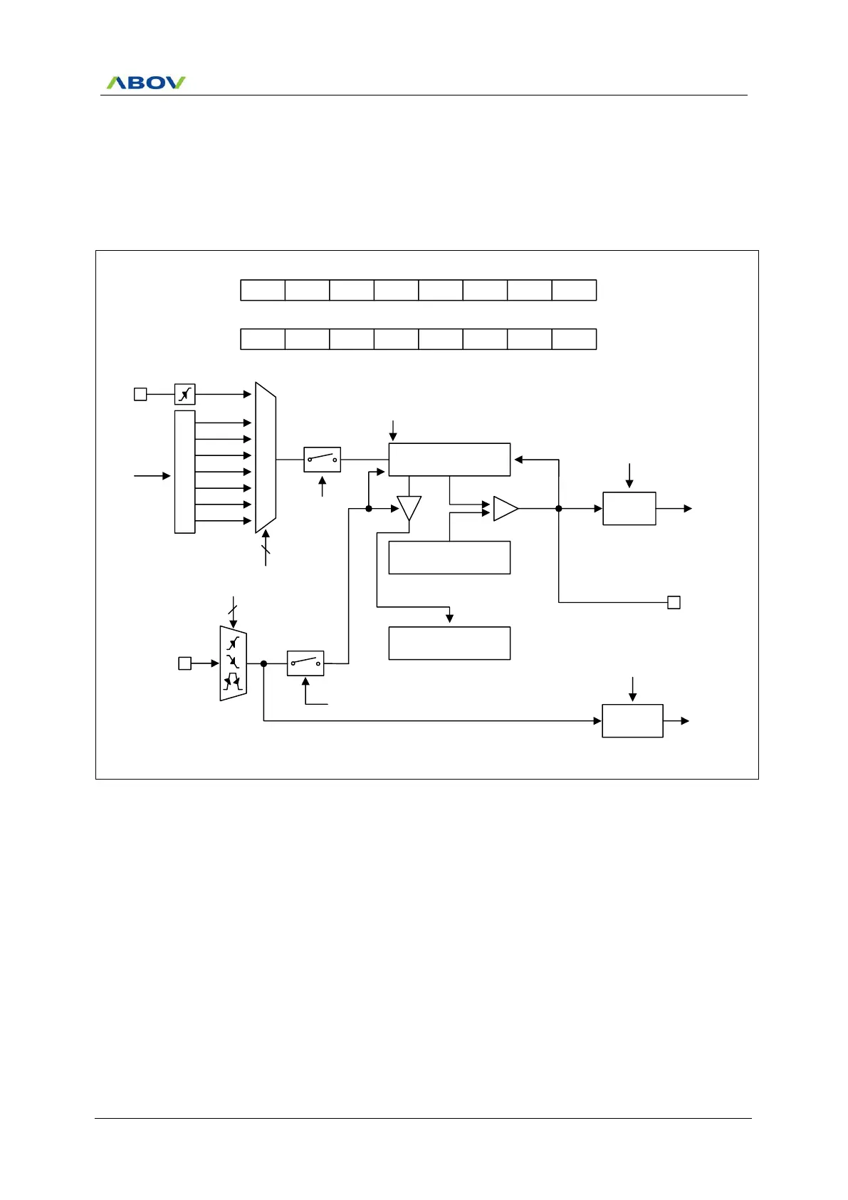
11.8.5 16-Bit Timer 3 Capture Mode
The 16-bit Capture mode is selected by control register as shown in Figure 11.33.
The 16-bit capture mode is the same operation as 8-bit capture mode, except that the timer register uses 16 bits.
The 16-bit timer 3 capture mode is set by T3MS, T4MS as ‘1’. The clock source is selected from T3CK[2:0] and
16BIT bit must be set to ‘1’. Timer 3 is LSB 8-bit, the timer 4 is MSB 8-bit.
P
r
e
s
c
a
l
e
r
fx
M
U
X
fx/2
T4CNT/T3CNT (16Bit)
EC3
fx/4
fx/8
fx/32
fx/128
fx/512
fx/2048
3
T3CK[2:0]
T3CN
16-bit Timer 3 Counter
T4DR/T3DR (16Bit)
Comparator
T3IFR
To interrupt
block
T3O
16-bit Timer 3 Data Register
INT_ACK
Clear
Clear
Match
T4CAPR/T3CAPR (16Bit)
Clear
EINT0
EIPOL0L[1:0]
FLAG0
(EIFLAG0.0)
S/W
Clear
To interrupt
block
2
T3MS
T3ST
16-bit Timer 3 Capture Register
MSB LSB
MSB LSB
MSB LSB
T3EN
T3CR
1
ADDRESS:1000H (ESFR)
INITIAL VALUE : 0000_0000B
–
T3MS T3CK2 T3CK1 T3CK0 T3CN T3ST
–
1 X X X X X
16BIT
T4CR
1
ADDRESS:1002H (ESFR)
INITIAL VALUE : 0000_0000B
T4MS T4CN T4ST T4CK3 T4CK2 T4CK1 T4CK0
1 X X
1
1 1 1
NOTE) The T4CR.7 bit (16BIT) should be set to ‘1’ and the T4CK[3:0] should be set to “1111b”.
Figure 11.33 16-Bit Capture Mode for Timer 3

 Loading...


