EasyManua.ls Logo

Abov MC96F6432 Series - Page 130

Abov MC96F6432 Series
327 pages
To Next Page IconTo Next Page
To Previous Page IconTo Previous Page
Loading...
MC96F6432
130 June 22, 2018 Ver. 2.9
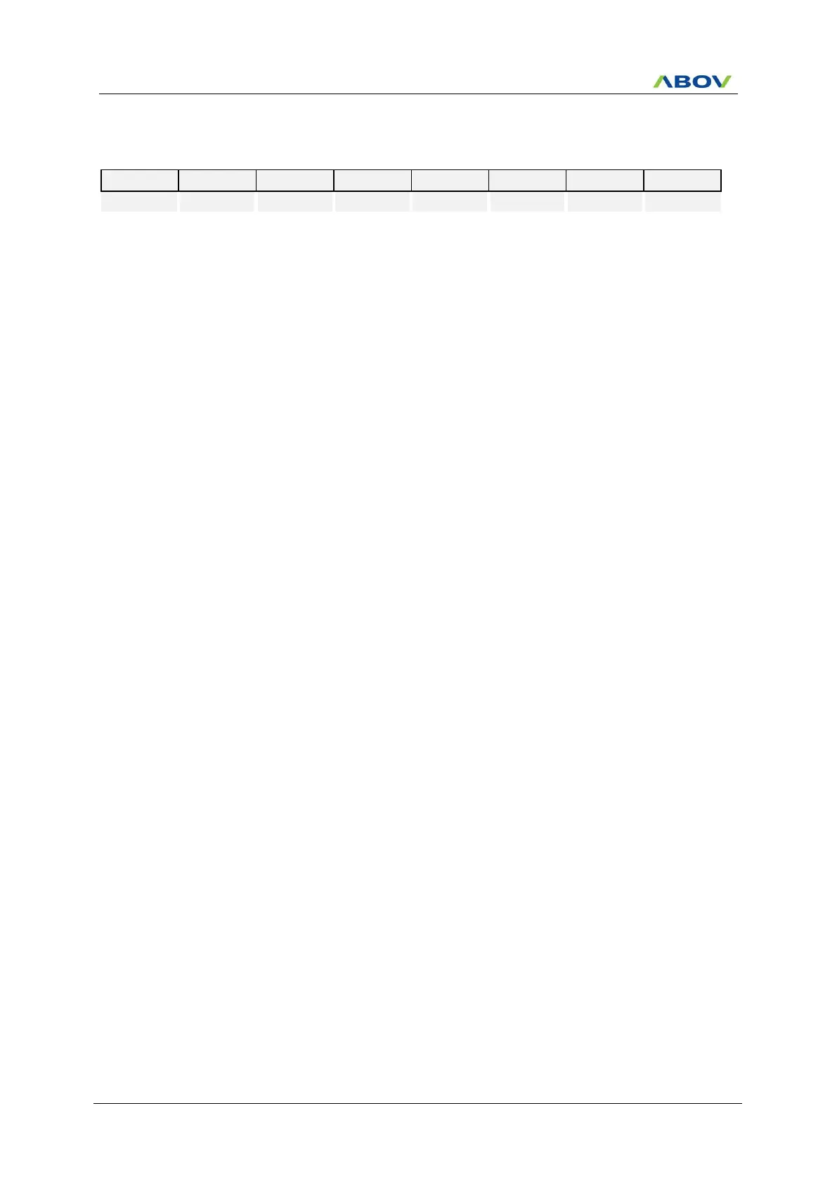
T0CR (Timer 0 Control Register) : B2H
7
6
5
4
3
2
1
0
T0EN
T0MS1
T0MS0
T0CK2
T0CK1
T0CK0
T0CC
R/W
R/W
R/W
R/W
R/W
R/W
R/W
Initial value : 00H
T0EN
Control Timer 0
0
Timer 0 disable
1
Timer 0 enable
T0MS[1:0]
Control Timer 0 Operation Mode
T0MS1
T0MS0
Description
0
0
Timer/counter mode
0
1
PWM mode
1
x
Capture mode
T0CK[2:0]
Select Timer 0 clock source. fx is a system clock frequency
T0CK2
T0CK1
T0CK0
Description
0
0
0
fx/2
0
0
1
fx/4
0
1
0
fx/8
0
1
1
fx/32
1
0
0
fx/128
1
0
1
fx/512
1
1
0
fx/2048
1
1
1
External Clock (EC0)
T0CC
Clear timer 0 Counter
0
No effect
1
Clear the Timer 0 counter (When write, automatically cleared
0 after being cleared counter)
NOTES) 1. Match Interrupt is generated in Capture mode.
2. Refer to the external interrupt flag 1 register (EIFLAG1) for the T0 interrupt flags.

Table of Contents

Related product manuals