MC96F6432
266 June 22, 2018 Ver. 2.9
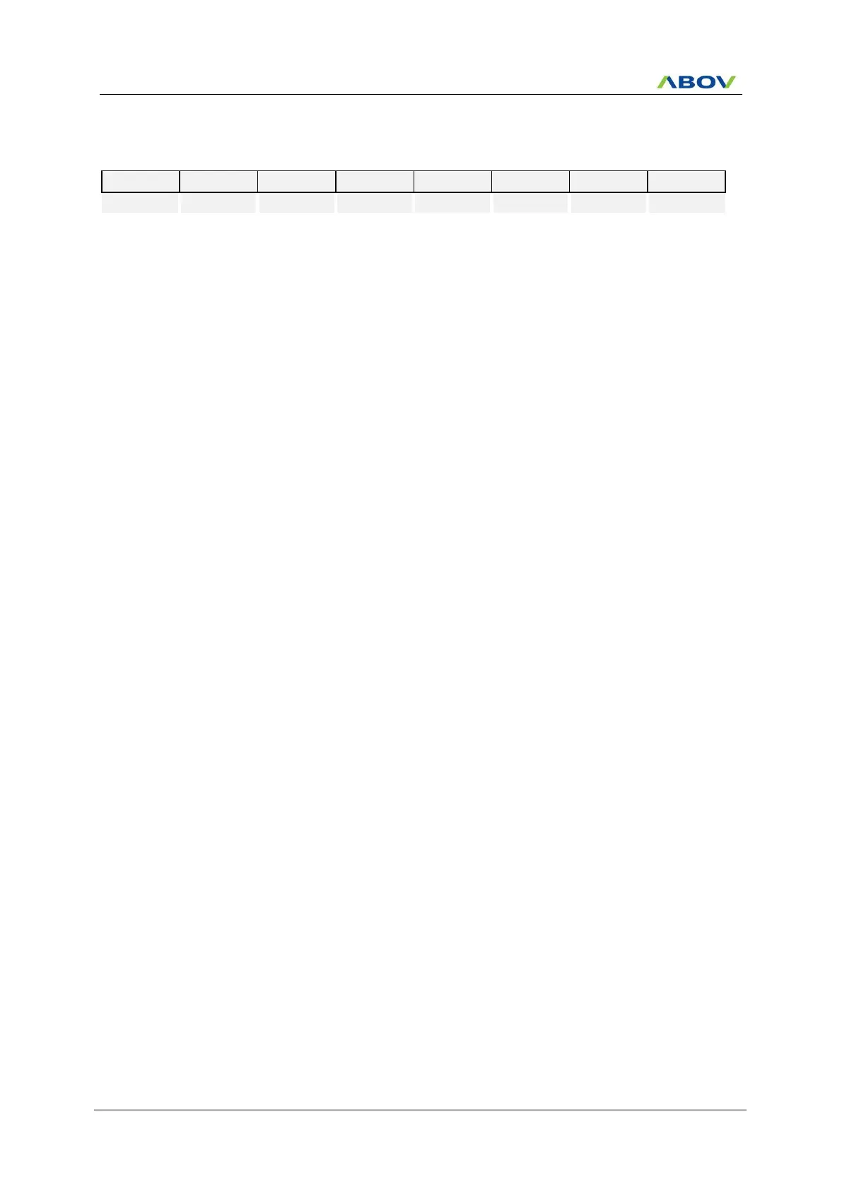
USI1CR4 (USI1 Control Register 4: For I2C mode) : ECH
Initial value : 00H
This is an interrupt flag bit for I2C mode. When an interrupt occurs, this
bit becomes ‘1’. This bit is cleared when all interrupt source bits in the
USI1ST2 register are cleared to “0b”. Writing “1” has no effect.
I2C interrupt no generation
USI1SDHR register control bit
Disable USI1SDHR register
Interrupt Enable bit for I2C mode
Interrupt from I2C is inhibited (use polling)
Controls ACK signal Generation at ninth SCL1 period.
No ACK signal is generated (SDA1 =1)
ACK signal is generated (SDA1 =0)
NOTES) ACK signal is output (SDA1 =0) for the following 3 cases.
1. When received address packet equals to USI1SLA bits in USI1SAR.
2. When received address packet equals to value 0x00 with GCALL1
enabled.
3. When I2C operates as a receiver (master or slave)
Represent operating mode of I2C
When I2C is master, STOP condition generation
STOP condition is to be generated
When I2C is master, START condition generation
START or repeated START condition is to be generated

 Loading...


