MC96F6432
16. Configure Option ........................................................................................................................................... 317
16.1 Configure Option Control ........................................................................................................................ 317
17. APPENDIX .................................................................................................................................................... 318
List of Figures
Figure 1.1 Debugger(OCD1/OCD2) and Pin description ........................................................................ 16
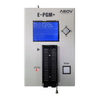
Figure 1.2 E-PGM+(Single writer) ........................................................................................................... 17
Figure 1.3 E-GANG4 and E-GANG6 (for Mass Production) ................................................................... 18
Figure 2.1 Block Diagram ....................................................................................................................... 19
Figure 3.1 MC96F6432L 48LQFP-0707 Pin Assignment ........................................................................ 20
Figure 3.2 MC96F6432Q 44MQFP-1010 Pin Assignment ...................................................................... 21
Figure 3.3 MC96F6332L 32LQFP Pin Assignment ................................................................................. 22
Figure 3.4 MC96F6332D 32SOP Pin Assignment .................................................................................. 23
Figure 3.5 MC96F6332M 28SOP Pin Assignment .................................................................................. 23
Figure 4.1 48-Pin LQFP-0707 Package .................................................................................................. 24
Figure 4.2 44-Pin MQFP Package .......................................................................................................... 25
Figure 4.3 32-Pin LQFP Package ........................................................................................................... 26
Figure 4.4 32-Pin SOP Package ............................................................................................................. 27
Figure 4.5 28-Pin SOP Package ............................................................................................................. 28
Figure 6.1 General Purpose I/O Port ...................................................................................................... 34
Figure 6.2 External Interrupt I/O Port ...................................................................................................... 35
Figure 7.1 AC Timing .............................................................................................................................. 43
Figure 7.2 SPI0/1/2 Timing ..................................................................................................................... 44
Figure 7.3 Waveform for UART0/1 Timing Characteristics ..................................................................... 45
Figure 7.4 Timing Waveform for the UART0/1 Module ........................................................................... 45
Figure 7.5 I2C0/1 Timing ........................................................................................................................ 46
Figure 7.6 Stop Mode Release Timing when Initiated by an Interrupt .................................................... 47
Figure 7.7 Stop Mode Release Timing when Initiated by RESETB ........................................................ 47
Figure 7.8 Crystal/Ceramic Oscillator ..................................................................................................... 49
Figure 7.9 External Clock ........................................................................................................................ 49
Figure 7.10 Crystal Oscillator .................................................................................................................. 50
Figure 7.11 External Clock ...................................................................................................................... 50
Figure 7.12 Clock Timing Measurement at XIN ...................................................................................... 51
Figure 7.13 Clock Timing Measurement at SXIN .................................................................................... 51
Figure 7.14 Operating Voltage Range .................................................................................................... 52
Figure 7.15 Recommended Circuit and Layout ....................................................................................... 53
Figure 7.16 Recommended Circuit and Layout with SMPS Power ......................................................... 54
Figure 7.17 RUN (IDD1 ) Current ........................................................................................................... 55
Figure 7.18 IDLE (IDD2) Current ............................................................................................................ 55
Figure 7.19 SUB RUN (IDD3) Current .................................................................................................... 56
Figure 7.20 SUB IDLE (IDD4) Current .................................................................................................... 56
Figure 7.21 STOP (IDD5) Current .......................................................................................................... 57
Figure 8.1 Program Memory ................................................................................................................... 59
Figure 8.2 Data Memory Map ................................................................................................................. 60
Figure 8.3 Lower 128 Bytes RAM ........................................................................................................... 61
Figure 8.4 XDATA Memory Area ............................................................................................................ 62
Figure 10.1 External Interrupt Description .............................................................................................. 94

 Loading...