Note that some of the connections - to the transceiver's BCD band data outputs and
Band Voltage outputs do not provide an exact frequency data, but only band data. Those
connections cannot be used when ACOM 700S works together with ACOM 04AT or 06AT
because the tuner needs to know the exact frequency, not only the band.
Besides the RS-232 and TTL compatible serial interface, the CAT connector also carries
the KEY IN and KEY OUT lines, which can be used instead of using separate cables for
those functions from the transceiver to the sockets of the same names.
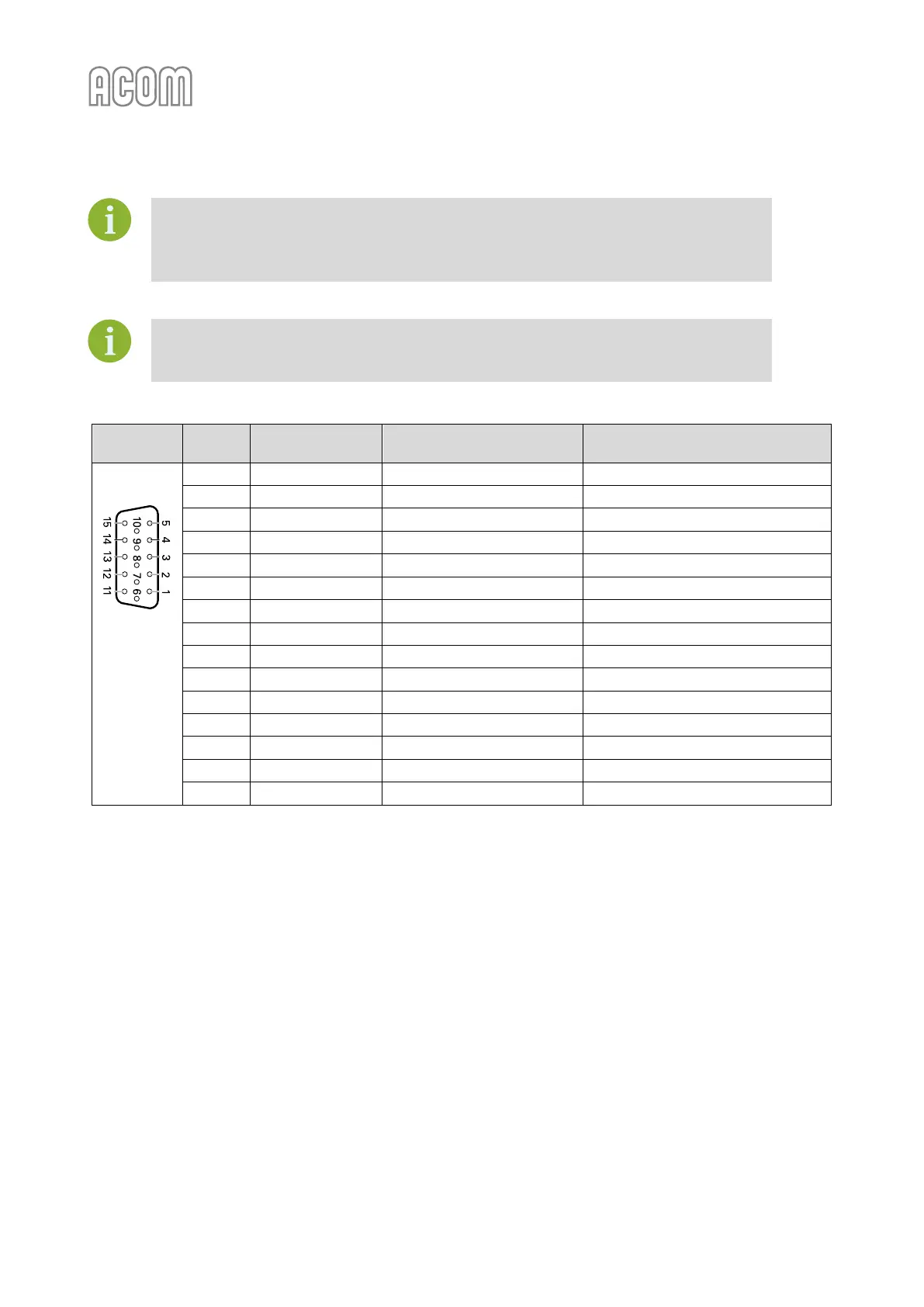
Table 2-2 | Signals and pin out of the CAT/AUX connector