EasyManua.ls Logo

Acom 700S - Table 2-3 | Signals and Pin out of the RS-232 Connector

Acom 700S
92 pages
Print Icon
To Next Page IconTo Next Page
To Previous Page IconTo Previous Page
Loading...
User's Manual | ACOM 700S | 1.8-54 MHz Linear Amplifier
April 2024
S e c t i o n INSTALLATION | Page 29 of 92
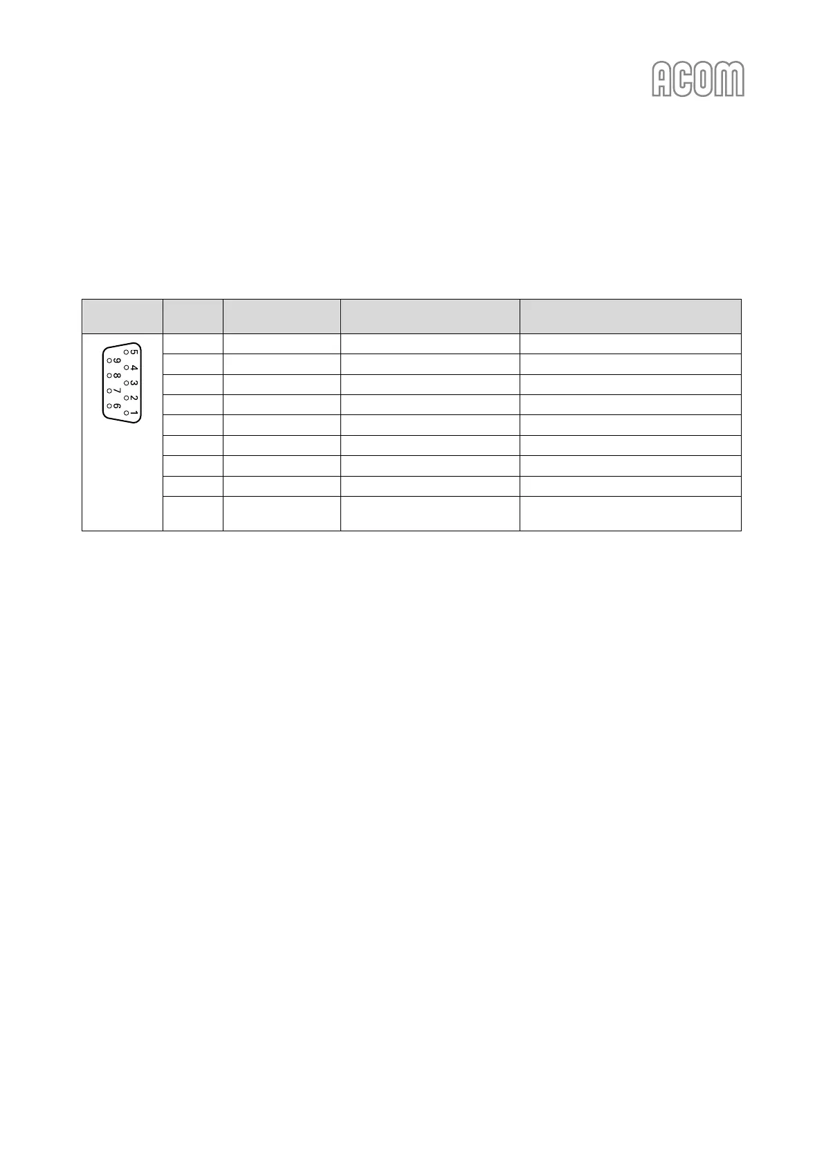
b) RS-232 interface connector
Please, see Figure 2-4 | Rear panel - Connections, Pos. (4).
RS-232 interface is used for Firmware Updates (see Section 7.5 Firmware) and for remote control (see
Section 6 REMOTE CONTROL).
Table 2-3 | Signals and pin out of the RS-232 connector
RS-232
interface
Pin Nr.
Pin name
Description
Specification
D-sub
connector,
9-pin,
female
(Rear panel
view)
1
-
Not connected
-
2
TxD
Transmit Data
RS-232 level output
3
RxD
Receive Data
RS-232 level input
4
-
Not connected
-
5
GND
Ground
0 Volt
6
DSR
Remote Power On
RS-232 level input
7
-
Not connected
-
8
CTS
Remote Power On
RS-232 level input
9
-
Not connected
-
Table 2-3 | Signals and pin out of the RS-232 connector

Table of Contents

Other manuals for Acom 700S

Related product manuals