F-1
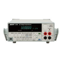
6146/6156 DC Voltage/Current Generators Operation Manual
LIST OF ILLUSTRATIONS
No. Title Page
1-1 Operating Environment ..................................................................................................... 1-5
1-2 Set Power Voltage Indicator ............................................................................................. 1-6
1-3 Power Cable ...................................................................................................................... 1-8
1-4 Connecting the Power Cable ............................................................................................. 1-9
1-5 Model Name and Software Revision Display ................................................................... 1-9
1-6 Model Name and Interface Display .................................................................................. 1-10
1-7 Start-up Screen .................................................................................................................. 1-10
2-1 Front Panel ........................................................................................................................ 2-1
2-2 Display Section ................................................................................................................. 2-2
2-3 RANGE Section ................................................................................................................ 2-2
2-4 OUTPUT CONTROL Section .......................................................................................... 2-3
2-5 POLARITY Section .......................................................................................................... 2-3
2-6 PROGRAM Section .......................................................................................................... 2-4
2-7 Other Keys ........................................................................................................................ 2-5
2-8 Output Section .................................................................................................................. 2-6
2-9 POWER Switch ................................................................................................................ 2-6
2-10 Screen Display (Annotations) ........................................................................................... 2-7
2-11 Rear Panel ......................................................................................................................... 2-8
2-12 Relation between Keys .....................................................................................................2-10
2-13 Menu Operation Overview ............................................................................................... 2-21
3-1 STBY IN ........................................................................................................................... 3-5
3-2 OPR/STBY IN .................................................................................................................. 3-5
3-3 INTERLOCK .................................................................................................................... 3-6
3-4 OPERATE OUT ............................................................................................................... 3-6
3-5 OPR SUS IN ..................................................................................................................... 3-6
3-6 Memory Recall Mode ....................................................................................................... 3-10
3-7 Sweep Source Mode ......................................................................................................... 3-10
4-1 Internal Wire Connection .................................................................................................. 4-1
4-2 2-Wire and 4-Wire Connections ....................................................................................... 4-2
4-3 Preventing Oscillation ....................................................................................................... 4-3
4-4 Source and Sink Zones ..................................................................................................... 4-3
4-5 Shifting between Operate, Standby and Suspend ............................................................. 4-13
4-6 Conceptual Diagram of Output Status .............................................................................. 4-14
4-7 Image of Grounded Load .................................................................................................. 4-16
4-8 Response Change by Limit Value for Voltage Source ..................................................... 4-19
4-9 Response Change by Limit Value for Current Source ..................................................... 4-20
4-10 TRIGGER IN Input Circuit .............................................................................................. 4-23
4-11 READY OUT/SYNC OUT Output Circuit ...................................................................... 4-24
4-12 OPERATE/STANDBY IN Signal and Its Output Status ................................................. 4-25
4-13 INTERLOCK Signal and Its Output Status ...................................................................... 4-26
4-14 OPERATE OUT Signal and Its Output Status ................................................................. 4-26
4-15 Connection for Three Unit Synchronous Operation Using OPERATE OUT .................. 4-27
4-16 Connection for Three Unit Synchronous Operation Using SYNC OUT .......................... 4-28

 Loading...