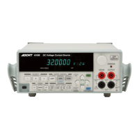
6146/6156 DC Voltage/Current Generators Operation Manual
2.1.3 Rear Panel
2-9
4. READY OUT | SYNC OUT
The output signal is a negative pulse.
The pulse width is about 10 ms.
The output circuit is TTL level open drain output and pulled up to
+5 V by 4.7 kΩ.
For more information, refer to Section 3.2.5, "MENU Key
(Parameter Setting)."
READY OUT :
Sends a synchronous signal to start measurement to the
external measuring instrument (such as DMM) after volt-
age/current output settling.
SYNC OUT :
Sends a signal synchronized with scan operation in the
memory recall mode or source output in the sweep source
mode.
5. INTERLOCK | OPERATE IN/OUT
The following five functions can be set on this terminal by menu
setting.
For more information, refer to Section 3.2.5, "MENU Key
(Parameter Setting)."
INTERLOCK :
The interlock signal is input. Sets Standby when the signal
level changes from LO to HI. The input resistance is
approximately 10 kΩ.
STBY IN:
Sets Standby when the signal level changes from LO to HI.
OPERATE OUT :
Sends Operate status with a level signal. The output circuit
(HI: Standby, LO: Operate) is TTL level open drain output
and pulled up to +5 V by 10 kΩ.
OPR/STBY In :
Switches between Operate and Standby when the signal
level changes from LO to HI. The input resistance is 10 kΩ.
OPR/SUS In :
Switches between Operate and Suspend when the signal
level changes from LO to HI. The input resistance is 10 kΩ.
CAUTION: When using the BCD remote, do NOT connect any
cables to the connector. It may cause malfunction.
6. GP-IB Port for connecting the GPIB cable to the external controller
7. USB Port for connecting the USB cable to the external controller
8. BCD Port for connecting the BCD cable to the external controller
CAUTION: This port is available only when the BCD interface
option is installed. (OPT6146+04/OPT6156+04)

 Loading...