Advanced RF Technologies, Inc.
2. OVERVIEW FOR EACH MODULE
2.1 NMS
2.1.1 LEDs
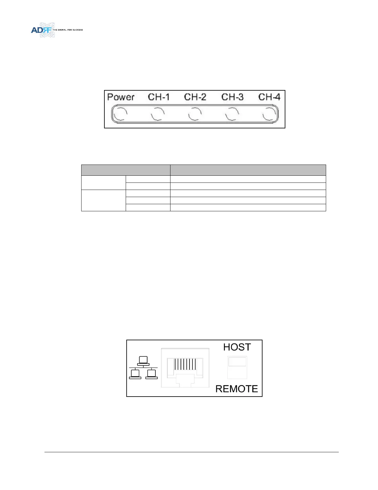
SDR has LEDs on the front of the NMS as shown below in Figure 3.
Figure 3 NMS LED
Table 2-1 NMS LED Specifications
Module has communication with NMS
Module has a communication failure with NMS
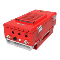
2.1.2 Ethernet Port and Host/Remote Switch
2.1.2.1 Ethernet Port
The Ethernet port can be used to communicate directly with the SDR using a RJ-45 crossover cable or can also
be used to connect the SDR to an external modem box.
2.1.2.2 Host/Remote Switch
The Host/Remote Switch allows the user to switch the default Repeater IP, Subnet Mask, and Gateway of the
repeater to an alternative setup. These settings can be adjusted by logging into the repeater in HOST mode and
configuring the settings under the Modem Box Setting section on the Install Page (section 5.4.1.3).
Once the settings are set, flipping the switch to the REMOTE position will reboot the repeater with the new
alternate settings. Please note that when the repeater is set to the REMOTE position, DHCP is disabled and the
repeater will not automatically assign an IP address to any device that connects directly to the repeater.
Figure 4 Ethernet Port and Host/Remote Switch
Host IP: 192.168.63.1 (Fixed IP, unable to modify this IP address)
Remote IP: 192.168.63.5 (Default IP, but can be modified in Host mode)