Advanced RF Technologies, Inc.
2.2.7 Communication Port & Mode Select Switch
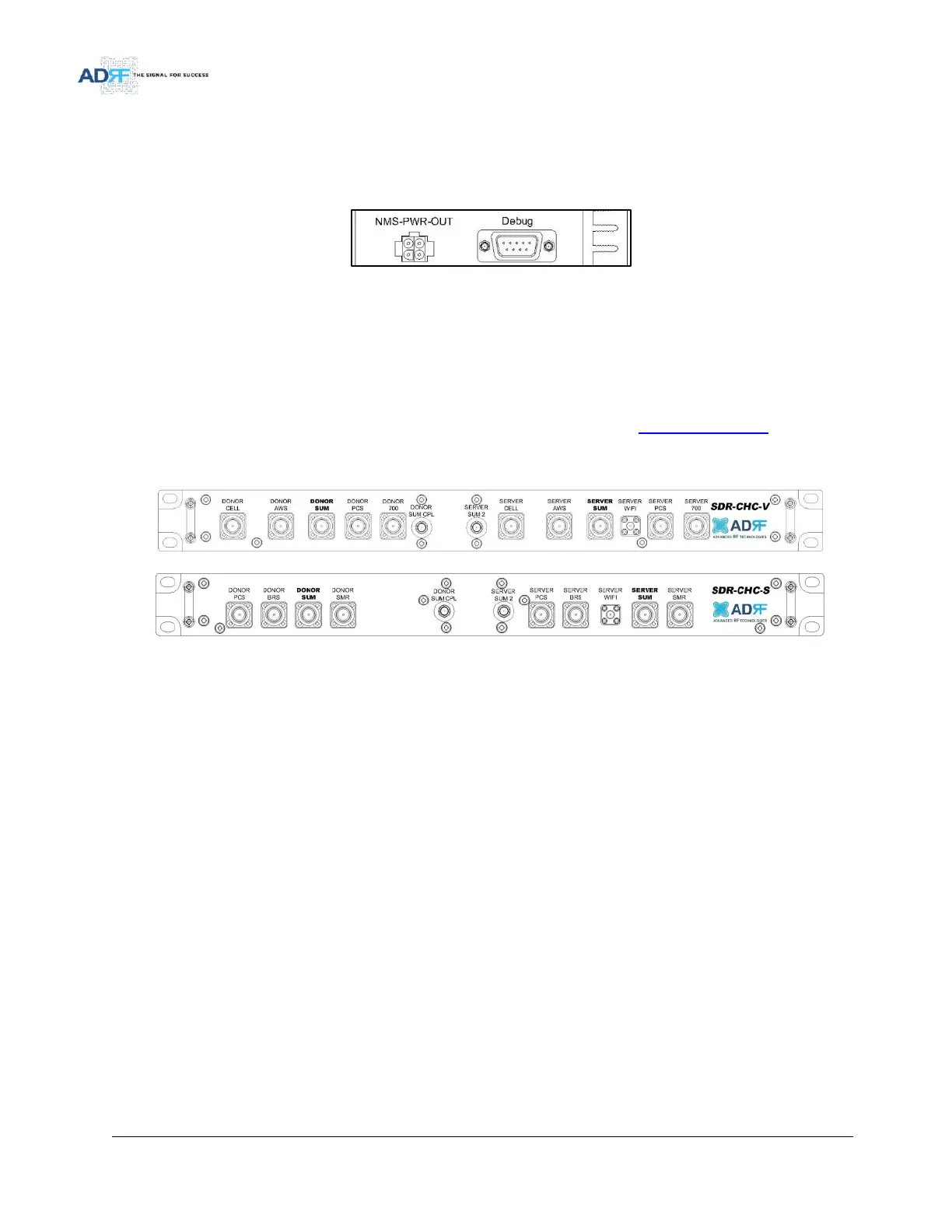
NMS-PWR-OUT- This port is used to power the SDR-NMS. If multiple modules are being used in a system, the
SDR-NMS only requires power from only 1 module. This port will connect to the NMS-PWN-IN on the SDR-NMS.
Debug Port- The debug port is used for ADRF testing purposes only.
Figure 15 NMS Power Port & Debug Port
2.3 Channel Combiner (SDR-CHC)
2.3.1 RF Ports
An optional channel combiner can be mounted directly above the SDR. There are 2 versions of the SDR-CHC.
The SDR-CHC-V supports Cellular, AWS, PCS, and 700MHz. The SDR-CHC-S supports PCS, BRS, and SMR. The donor
portion of the SDR-CHC can be used to split up a combine donor signal. The server portion of the SDR-CHC can be
used to combine the server signals into the Server Sum port. Please contact sales@adrftech.com if you are
interested in purchasing the SDR-CHC.
Figure 16 Channel Combiner RF ports
Port Name Description
- Donor PCS: Connects to the SDR PCS donor port
- Donor Cell: Connects to the SDR Cell donor port
- Donor AWS: Connects to the SDR AWS donor
port
- Donor 700: Connected to the SDR 700 MHz
donor port
- Donor BRS: Connects to the SDR BRS donor port
- Donor Sum: Connects to the combined donor
line
- Donor SMR: Connects to the SDR SMR donor
port
- Donor Sum CPL: Expansion donor port with 18
dB ±3 coupling value [Connects to an external
modem box]
- Server Sum 2: Expansion server port with 20 dB
coupling value
- Server PCS: Connects to the SDR PCS server port
- Server Cell: Connects to the SDR Cell server port
- Server AWS: Connects to the SDR AWS server
port
- Server 700: Connects to the 700 MHz server port
- Server BRS: Connects to the BRSPCS server port
- Server WiFi: Input port for Wifi AP
- Server Sum: Connects to the server antennas
- Server SMR: Connects to the SDR SMR server
port