Advanced RF Technologies, Inc.
5.3.2.4 Alarm Reporting Time
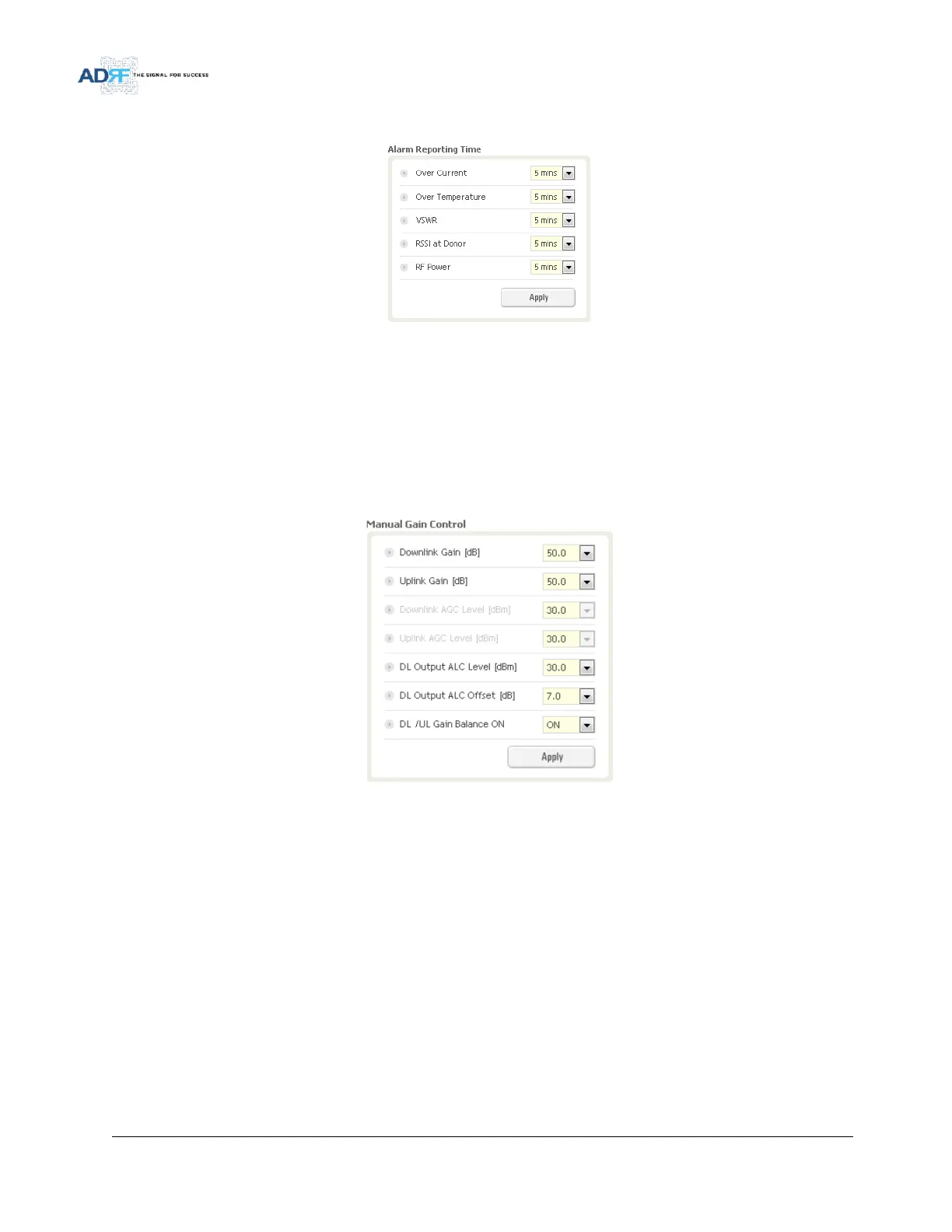
Figure 52 Alarm Reporting Time Setting
This section allows the user to specify the reporting time of the following alarms; Over Current, Over
Temperature, VSWR, RSSI at Donor, and RF Power. If the alarm is set to 5 mins, then the system will send out a
SNMP trap only if the alarm is continually present for a 5 minute period. If the alarm clears within this 5 minute
period, then the SNMP trap will not be sent out. When the alarm reporting time is set to 0 min, the SNMP trap will
be set out immediately once the alarm is triggered. The alarm should be set to 0 min, only when testing the
monitoring function. Otherwise, all alarms should be set to 5 mins for normal operation.
5.3.2.5 Manual Gain Control
Figure 53 Main Gain Control Setting
Downlink Gain: Allows the DL gain to be adjusted manually when AGC is OFF
Uplink Gain: Allows the UL gain to be adjusted manually when AGC is OFF
Downlink AGC Level: Allows the user to set the DL output power level when AGC is enabled
o The system will automatically adjust the gain levels to output the specified AGC level
Uplink AGC Level: Allows the user to set the UL output power level when AGC is enabled
o The system will automatically adjust the gain levels to output the specified AGC level
DL Output ALC Level: Allows the user to set the Max output level when AGC is OFF
DL Output ALC Offset: The delta value at which the BDA will increase/decrease the gain levels to compensate
for the decrease/increase in signal level
DL /UL Gain Balance ON: When enabled, the system will keep the delta value between the Downlink and Uplink
gain levels