Advanced RF Technologies, Inc.
2.2 RF Module
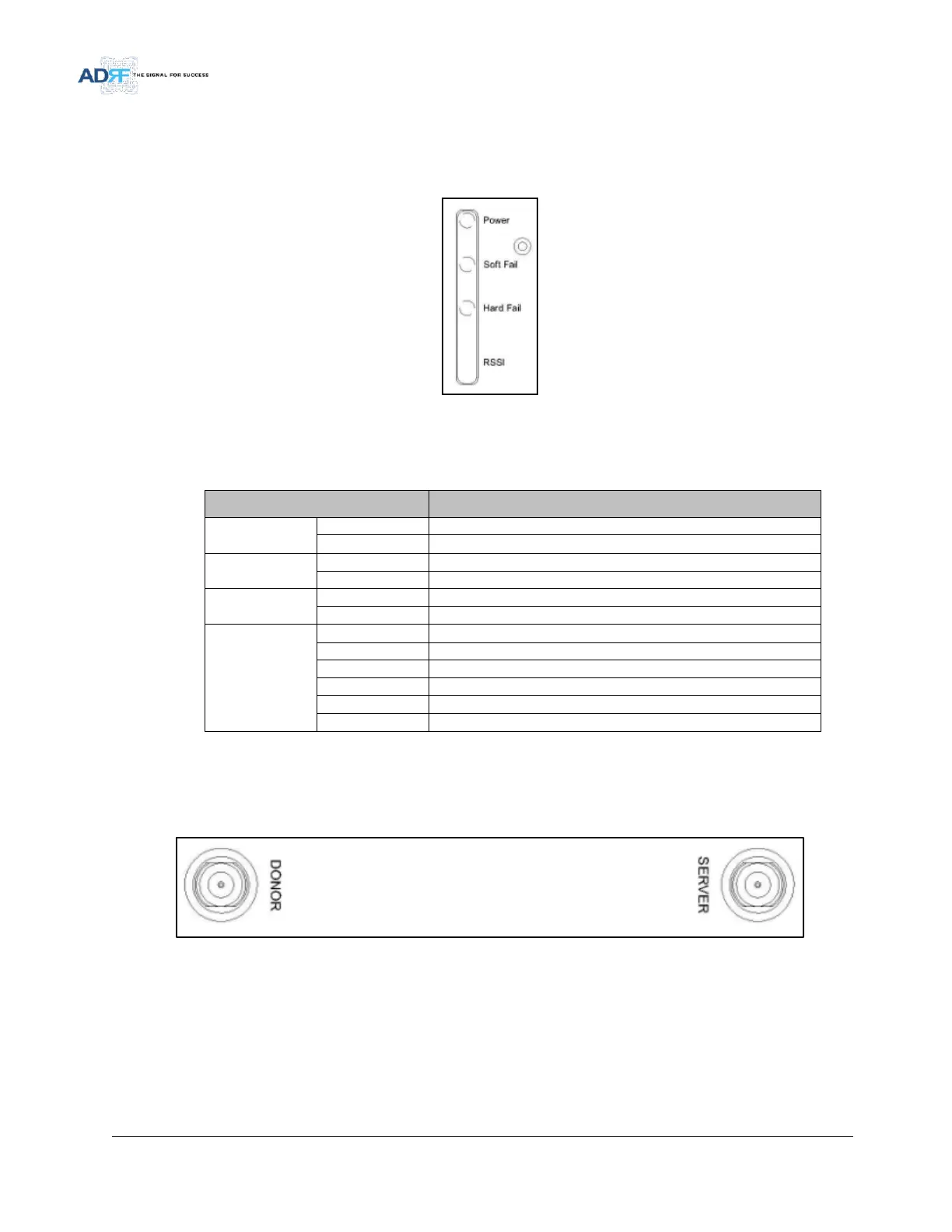
2.2.1 LEDs
SDR has LEDs on the front of the RF module as shown below in Figure 9.
Figure 9 RF Module LED
Table 2-2 RF Module LED Specifications
Soft Fail alarm exist in the system
No Soft Fail alarm are present in the system
Hard Fail alarm exist in the system
No Hard Fail alarms are present in the system
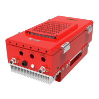
2.2.2 RF Ports
Donor and server antennas can be connected directly to the modules or the optional SDR-CHC (channel
combiner) can be used to split or combine signals.
Figure 10 RFU RF port