Advanced RF Technologies, Inc.
3.2 Alarms
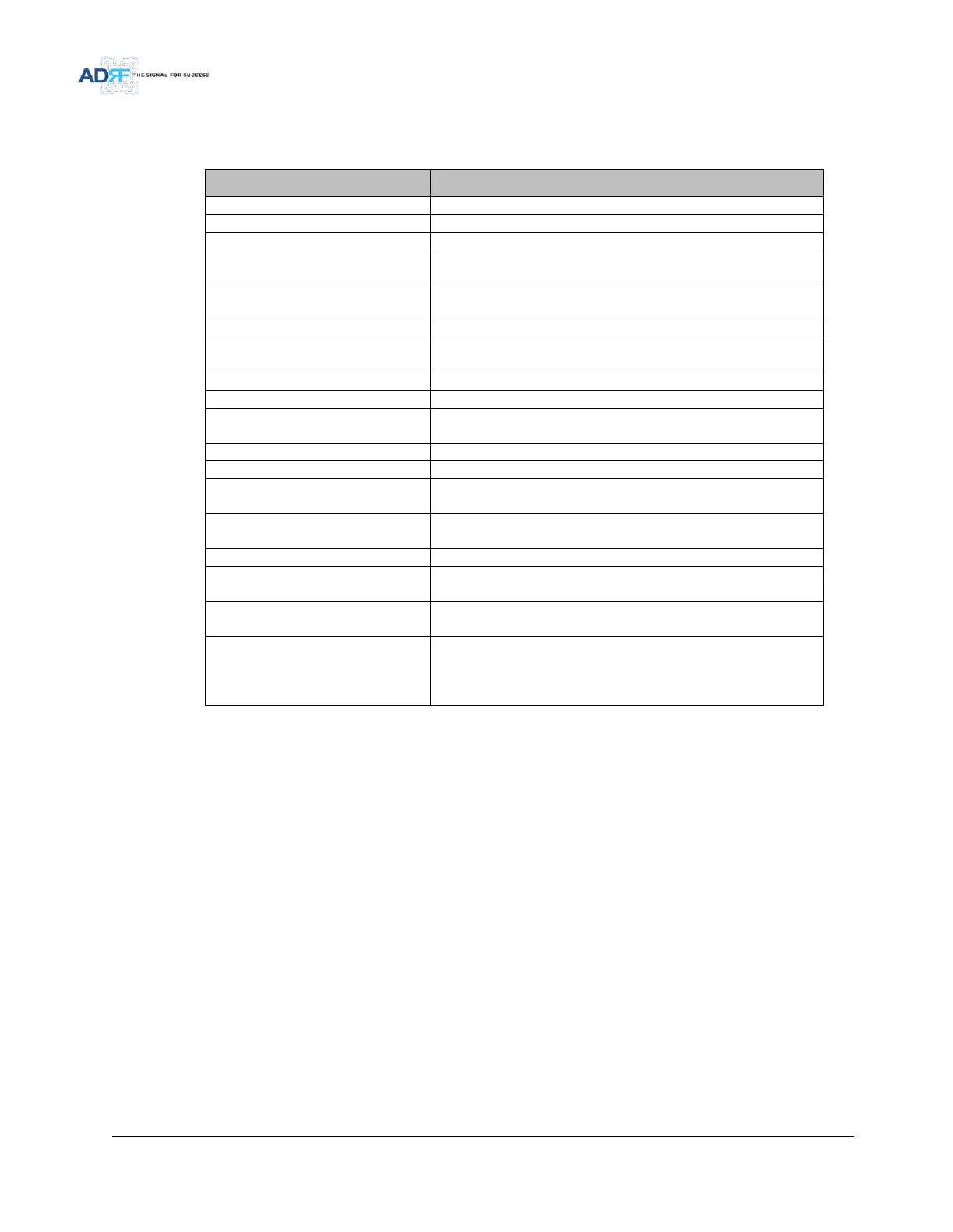
Table 3-2 Alarms Threshold
Power supply is not operating within specs. (4 seconds)
Power supply is not operating within specs. (4 seconds)
System has detected an issue with the fan. (4 seconds)
Module is above the normal operating temperature. (4 seconds)
Over Temperature [ Soft: 80~87 C, Hard: Above 87 C]
Power supply is not operating within specs. (4 Second)
Over Current [ Hard: Above 10A]
System is in a shutdown state due to a hard fail alarm. (10 times)
System has detected an issue with the internal DSP chip. (Cannot
communication with DSP)
Communication error between the module and NMS. (5 mins)
Unable to perform TDD sync (10 seconds)
Oscillation detected. Alarm is only present when one-time
oscillation check is performed (4 seconds)
DL signal is below the specified level. (default: -85dBm)
DL signal is below the specified level. (default: -90dBm)
Input signal is above the threshold.
(Soft: -17dBm, Hard: -15dBm)
Out of band signal is above the threshold.
(Soft: -17dBm, Hard: -15dBm)
Input + gain does not match the output level
(default delta of 6 dB)
Output level is above the max output levels
(Soft: ALC or AGC + 1~2dB, Hard: ALC or AGC + >2dB)
Power is being reflected back to the repeater. Threshold = output
power - 8dB. For example, if the repeater is outputting 24dBm,
then if the system detects 16dBm of return power, then the VSWR
will be triggered.