325025PM Rev2
(3255 Service Manual)
Page 2 of 6
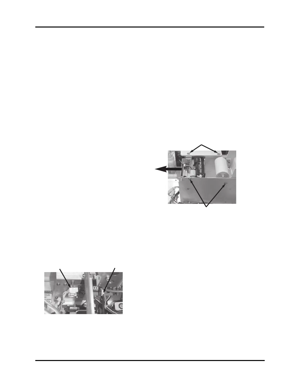
data cable (B) attached at the lower rear of
the printer assembly, then disconnect the
printer power connection (C) located in the
middle side of the printer interface PCB,
towards the sample cooling assembly and
head.
3. Remove the two mounting screws (D) that
attach the printer bracket to the deck.
4. Mark the front-to-back position of the
mounting screws (E) that attach the printer
bracket to the main PCB mounting bracket
with a fine tip marker to assist during
reassembly, then remove the two mounting
screws.
Note: The printer cover should be released
and open before removing the four
screws (A) that release the instrument
cover.
4. Attach the static grounding strap to your
wrist and stick the adhesive end to a suit-
able bare-metal ground, such as the rear
panel.
Remove the Control Board Set:
1. Tilt the keypad forward to provide access
and clearance to the printer assembly.
Remove the installed paper roll from the
printer assembly.
2. Remove all wiring connections to the
application board (larger of two).
3. Gently pry the board set off the four
snap-on standoffs.
Note: Some instruments may require two
screws be removed prior to removing
the board set.
Remove the Printer Assembly:
1. Locate the printer assembly mounted
between the deck and the main PCB sup-
port. This includes the mounting bracket,
the printer mechanism, printer control
PCB, the printer interface PCB, and the
interconnecting cable.
2. Release the cable end latch by pressing
firmly on the cable end connector closest
to the wires and disconnect the printer
5. To remove the printer assembly, slide the
printer assembly towards the front of the
instrument until the printer bracket is
clear of the deck. Set aside until reinstal-
lation.
Main Harness Replacement:
1. Remove the two cable ties (F) that hold
the main harness to the chassis. Remove
the two cable ties dressing the connection
to the head cable and cooling assembly.
2. Disconnect all of the main harness con-
nectors still attached after being discon-
B
C
D
E