325025PM Rev2
(3255 Service Manual)
Page 3 of 6
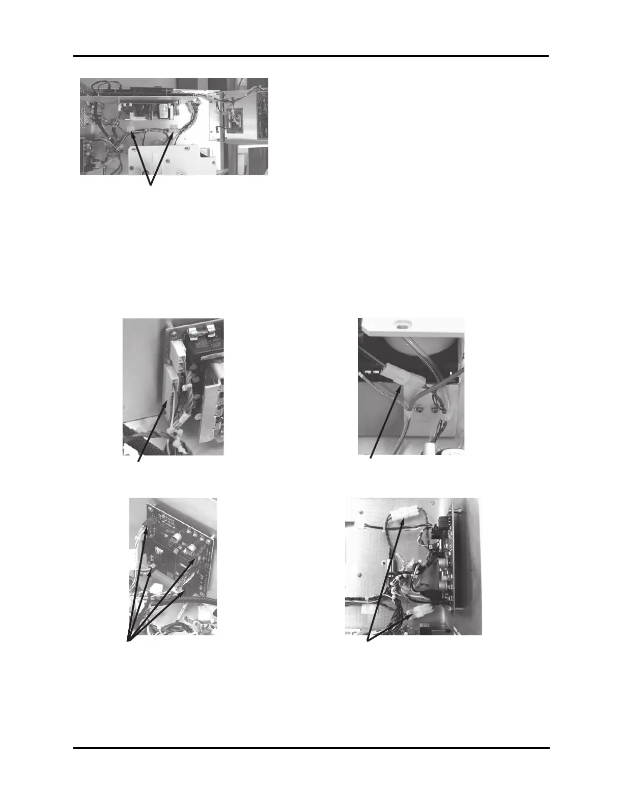
Power Supply Connection
nected from the control board set, then
remove the main harness.
Note: Some of the connectors are latched
and must have the latch released
before disconnecting. Use care when
disconnecting to avoid damage to the
components and circuit boards.
3. Visually examine the connector pins on
the power supply. If there are any signs
of discoloration to the header or if some
of the pins do not appear shiny, contact
the Advanced Instruments Service Center
for replacement of the power supply.
4. Position the replacement main harness as
shown, then connect all of the connectors.
The connections to the control board set
will be made after the replacement board
set is installed.
Note: The force required to seat the power
supply connector will be significantly
greater than the old harness.
F
Driver Board Connections
Cooling Assembly Connections
Load Resistor Connections