325025PM Rev2
(3255 Service Manual)
Page 4 of 6
3. Connect the printer power connection (C)
to the connector on the bottom of the
printer interface board, then connect the
printer data cable (B) to the connection at
the lower rear of the printer assembly.
4. Return the keypad back to the normal
position, making sure no wires are being
pinched.
Install the Replacement Control Board Set:
1. Remove the replacement board set from
its anti-static bag.
5. Secure the main harness in place using
two cable ties. Dress the connections to
the head cable and cooling assembly
using two cable ties to prevent these
wires from getting pinched by the keypad
assembly when it is closed. Use a wire
cutter to trim the cable ties.
Reinstall the Printer Assembly:
1. Install the printer assembly back into the
instrument by guiding it back into posi-
tion from the front of the instrument.
Replace the printer bracket mounting
screws, making sure to position the print-
er bracket as noted during the disassem-
bly, earlier. This location is important to
ensure proper alignment to the instrument
cover.
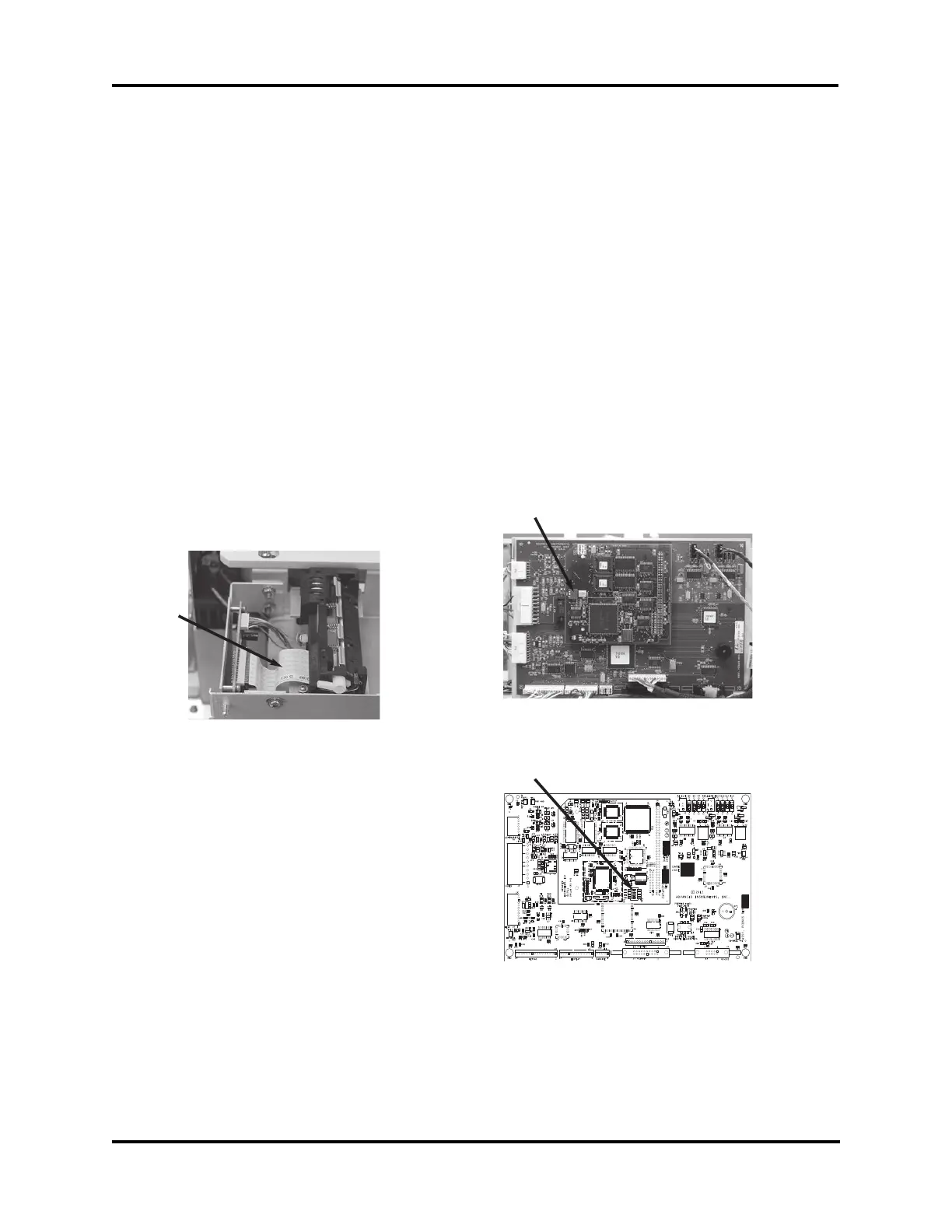
2. Make sure the printer flex cable (G) is
positioned as shown.
2. Check and confirm the correct setting of
the options/configuration switch SW1 (H),
located on the processor board (smaller of
two).
• For a 3250 with a 3-position switch,
the settings should be ON, ON, OFF.
• For a 4250 with a 3-position switch,
the settings should be OFF, ON, OFF.
• For a 3250 with a 4-position switch,
the settings should be OFF, ON, ON,
OFF.
• For a 4250 with a 4-position switch,
the settings should be OFF, ON, OFF,
OFF.
Note: Markings on switch body may vary:
ON = 1 = CLOSED |
OFF = 0 = OPEN.
G
H
H
Updated Board Set
Two-Board Set