325P350 Rev1
(4D35/3255/MK05 Service Manual)
Page 2 of 4
14. Reconnect the three motor connectors
(A), making sure to reconnect in the same
configuration as noted in Step 4.
15. Reconnect the harness to the connector at
the bottom of the Head Up/Down PCB
(B).
16. Replace the instrument cover, then secure
in place using the mounting screws.
325304R Instruction:
Refer to Figures 3, 4 and 5.
1. Turn off the power and unplug the instru-
ment.
2. Remove the screws securing the instru-
ment cover, and remove the cover.
3. Place an empty sample tube in the sample
well, then push the head down.
4. Disconnect the motor connector (G) from
the driver PCB located on the inside rear
of the instrument.
Figure 3
the clutch assembly. If necessary, use a
screwdriver to gently pry the clutch
assembly from the shaft.
9. Remove the four screws (F) that secure
the motor to the bracket, and remove the
motor.
10. Assemble the replacement motor to the
motor mounting bracket using the four
screws (F).
11. Slide the clutch assembly onto the
replacement motor shaft and tighten the
two Allen setscrews, making sure to
locate the clutch assembly per the meas-
urement taken in Step 8.
12. Install the motor assembly into the instru-
ment using the two screws (D) through
the surface of the deck. Make sure the
teeth of the plastic gear are properly
meshed with the gear rack on the sample
head shaft, and the motor mounting
bracket is pressed firmly against the
lower back surface of the deck casting.
Tighten the two screws.
13. Install and tighten the two motor assem-
bly mounting screws (C) below the deck.
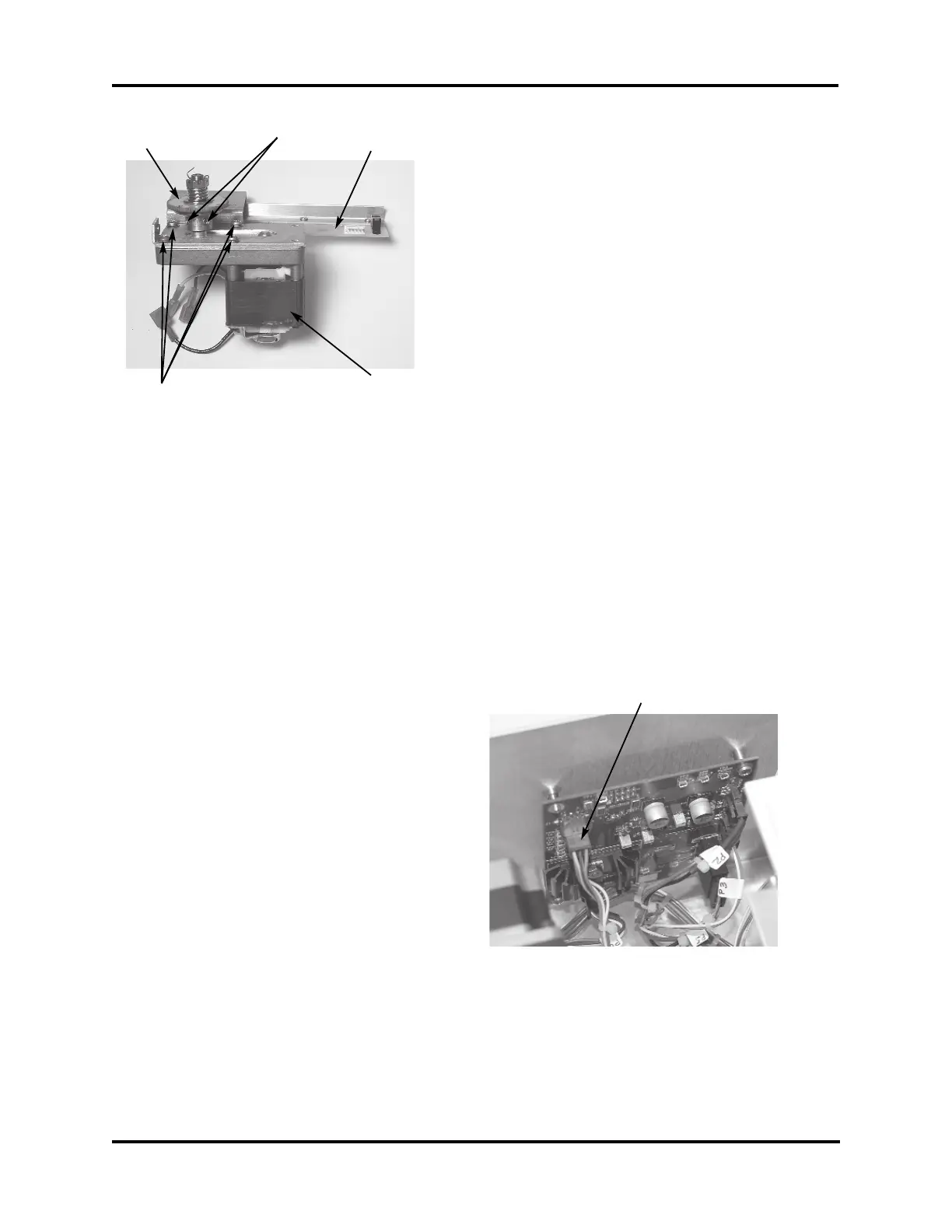
Figure 2
E
Motor
Head Up/
Down PCB
Clutch
Assembly
F
G