325P350 Rev1
(4D35/3255/MK05 Service Manual)
Page 3 of 4
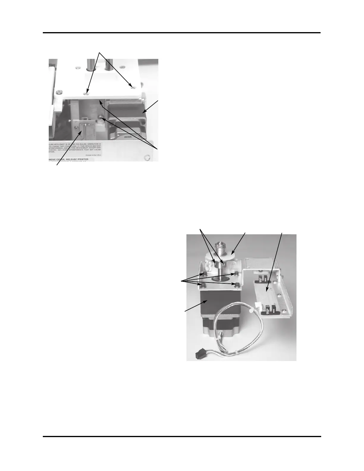
5. Disconnect the harness connected to the
bottom of the Head Up/Down PCB (not
shown).
6. Remove the motor assembly mounting
screws (H) below the deck. A short or
right-angle screwdriver may help to
access these screws.
7. Remove the motor assembly mounting
screws (I) through the top surface of the
deck, then lift the motor assembly out of
the instrument and place on a flat, clean
surface near the instrument.
8. Measure the space between the plastic
gear on the clutch assembly to the surface
of the motor mounting bracket so that it
can be replaced in the same location on
the replacement motor. Using the 1/16”
Allen wrench, remove the two Allen
setscrews (J) that secure the clutch
assembly to the motor shaft, then remove
the clutch assembly. If necessary, use a
screwdriver to gently pry the clutch
assembly from the shaft.
9. Using the 9/64” Allen wrench, remove
the four screws (K) that secure the motor
to the bracket, and remove the motor.
10. Assemble the replacement motor to the
motor mounting bracket using the four
screws (K).
11. Slide the clutch assembly onto the
replacement motor shaft and tighten the
two Allen setscrews, making sure to
locate the clutch assembly per the meas-
urement taken in Step 8.
12. Install the motor assembly into the instru-
ment using the two screws (I) through the
surface of the deck. Make sure the teeth
of the plastic gear are properly meshed
with the gear rack on the sample head
shaft, and the motor mounting bracket is
pressed firmly against the lower back sur-
face of the deck casting. Tighten the two
screws.
Figure 4
Figure 5
I
Motor
H
Head Up/
Down PCB
Clutch
Assembly
J
Head Up/
Down PCB
Motor
K