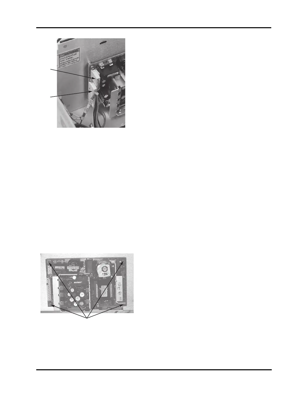
5. Disconnect the AC power harness (F) and
the main harness DC power connector (G)
from the power supply.
6. Remove the power supply by removing the
four (4) mounting screws (H) located at the
corners of the power supply.
Note: If necessary, the power supply/main
PCB mounting bracket can be removed
by removing the two mounting screws
from the rear of the instrument, and the
two mounting screws located in the bot-
tom flange of the mounting bracket at
either end. Carefully tilt the bracket to
access the power supply, taking care not
to damage the main PCB located on the
other side of the bracket.
7. Install the replacement power supply on
the mounting bracket, making sure to
maintain the same orientation, with the
connections toward the rear of the instru-
ment. Reinstall the power supply/main
PCB mounting bracket, if necessary.
8. Connect the main harness DC power con-
nector (the larger of the two connectors)
to the new power supply, then connect the
AC power harness.
9. Reinstall the printer assembly into the
instrument by guiding it back into posi-
tion from the front of the instrument.
Replace the printer bracket mounting
screws, making sure to position the print-
er bracket as noted during the disassem-
bly, earlier. This location is important to
ensure proper alignment to the instrument
cover.
10. Remount the main PCB on the mounting
standoffs, taking care not to bend or
stress the main PCB. Reinstall two
screws, if applicable.
11. Connect the printer power connection to
the connector on the bottom of the printer
interface board, then connect the printer
data cable to the connection at the lower
rear of the printer assembly.
12. Replace the instrument cover, taking care
to align the cover so that there is space on
either side of the printer cover, then
secure with the screws.
13. Replace the head cover, then secure with
the screws.
14. Reinstall the printer paper roll per the
instructions in the User’s Guide.
325P950 Rev2
(4D35/3255/MK05 Service Manual)
Page 3 of 3
H
F
G