325420PM Rev1
(3255 Service Manual)
Page 2 of 3
instrument until the printer bracket is
clear of the deck.
10. Transfer the following parts to the
replacement printer assembly, as follows:
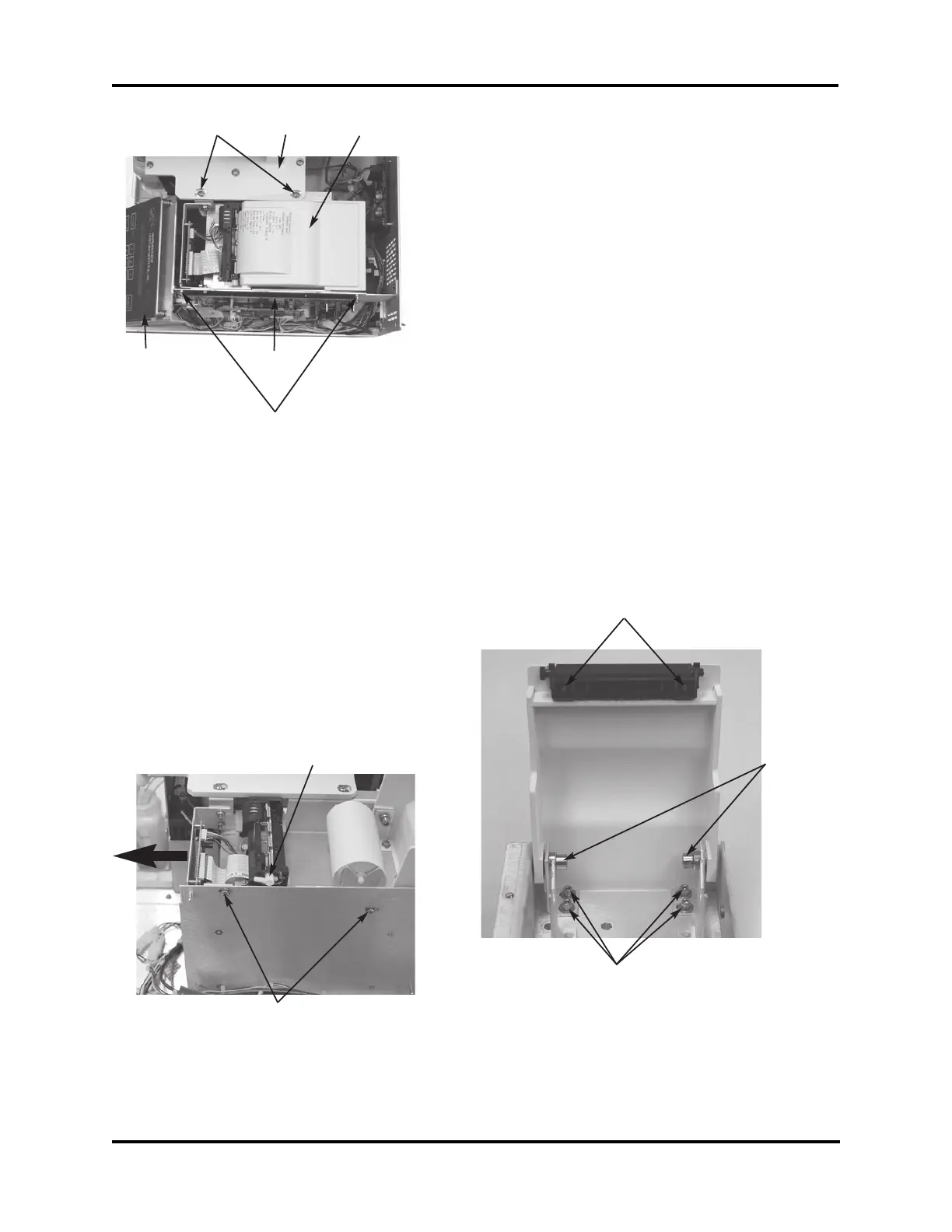
a. Depress the printer door release lever
(F) and open the printer door fully.
b. Remove the printer door pivot screws
(G), then remove the printer door.
c. Remove the printer platen mounting
screws (H), then remove the printer
platen from the printer door.
d. Release the printer platen from the
replacement printer assembly by press-
ing the release lever on the printer.
Install the replacement printer platen
onto the printer door.
e. Remove the printer door support
bracket mounting screws (I), then
install the printer door support bracket
in the replacement printer assembly.
Tighten the screws only enough to
7. Remove the two mounting screws (C) that
attach the printer bracket to the deck.
8. Release the main PCB from the standoffs
(D). Some instruments may require two
screws be removed. Tilt the main PCB
away from the mounting bracket. Note the
front-to-back position of the mounting
screws (E) that attach the printer bracket to
the main PCB mounting bracket to assist
during reassembly, then remove the two
mounting screws.
9. To remove the printer assembly, slide the
printer assembly towards the front of the
C
D
Deck Printer Cover
Keypad Main PCB
E
F
I
G
H