325420PM Rev1
(3255 Service Manual)
Page 3 of 3
hold the brackets in place, but still
allow them to be moved on the printer
mounting bracket.
f. Position the printer door, then install
the printer door pivot screws.
g. Close the printer door, making sure the
platen is fully engaged in the printer
mechanism. Allow the printer mecha-
nism to guide the position of the door,
moving the printer door support brack-
ets as needed. Once adjusted, tighten
the printer door support bracket
mounting screws.
h. Test the open/close action of the print-
er door by pressing the printer door
release lever, then swinging the printer
door back, then re-engaging the printer
door into the printer mechanism. The
printer door should move freely in and
out of the printer mechanism with a
distinct latching or release action, but
without binding. If necessary, loosen
and adjust the printer door support
brackets until the action is acceptable.
11. Install the replacement printer assembly
into the instrument by guiding it back
into position from the front of the instru-
ment. Replace the printer bracket mount-
ing screws, making sure to position the
printer bracket as noted during the disas-
sembly, earlier. This location is impor-
tant to ensure proper alignment to the
instrument cover.
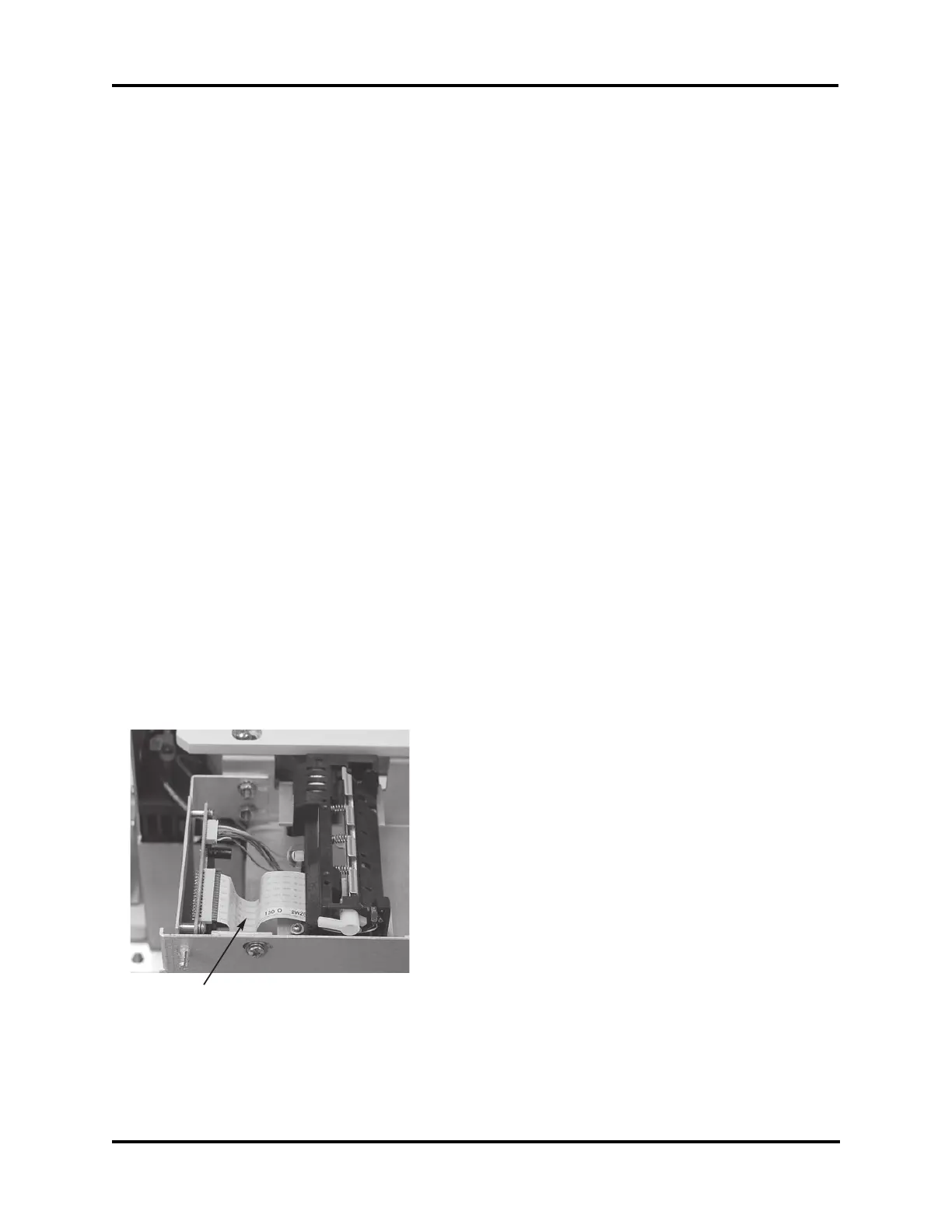
12. Make sure printer flex cable (J) is posi-
itoned as shown.
13. Remount the main PCB on the mounting
standoffs, taking care not to bend or
stress the main PCB. Reinstall two
screws, if applicable.
14. Connect the printer power connection to
the connector on the bottom of the printer
interface board, then connect the printer
data cable to the connection at the lower
rear of the printer assembly.
15. Replace the instrument cover, taking care
to align the cover so that there is space on
either side of the printer cover, then
secure with the screws.
16. Replace the head cover, then secure with
the screws.
17. Reinstall the printer paper roll per the
instructions in the User’s Guide.
J