3LP700 Rev10
(4C35/4D35/3255/MK05 Service Manual)
Page 2 of 5
Model 4C3 multi-sample cryoscope is essen-
tially the same as what is described here for
the single-sample osmometer or cryoscope.
CAUTION: Turn off the osmometer or
cryoscope while making the fol-
lowing checks or adjustments.
General Instructions:
1. Remove the head cover.
2. Before checking the probe or stir wire
alignment, make sure the mandrel is posi-
tioned and aligned, as follows (refer to
Figures 1 and 2):
a. Make sure there is no gap between
the top of the mandrel flange and the
bottom of the sample head.
b. Look to see if the stir wire slot in the
mandrel is aligned so that it is perpen-
dicular with the front edge of the
sample head (Figure 2).
c. If adjustments are necessary, while
supporting the mandrel loosen the two
mandrel setscrews in the head, make
the adjustments, then carefully
retighten the mandrel setscrews.
Osmometer Instructions:
1. Facing the instrument from the front,
slide the alignment tool squarely up onto
the mandrel, round-end first, with the
stir/freeze wire located as shown in
Figure 3.
2. Check the probe alignment by making
sure that the probe shaft is lined up along
the raised V centerline of the alignment
tool and the probe level by making sure
that the end of the probe rests on the hori-
zontal surface below the raised V center-
line, as shown in Figure 3.
3. If necessary, make probe centering adjust-
ments. Bend the metal probe stem gently
by hand, as necessary, to align the probe
along the raised V centerline of the probe
alignment tool.
4. If necessary, make probe vertical adjust-
ments:
a. Loosen the probe setscrew (Figure 1)
and then raise or lower the probe
within its mandrel, as necessary.
b. When the bottom of the probe is
exactly level with the horizontal step,
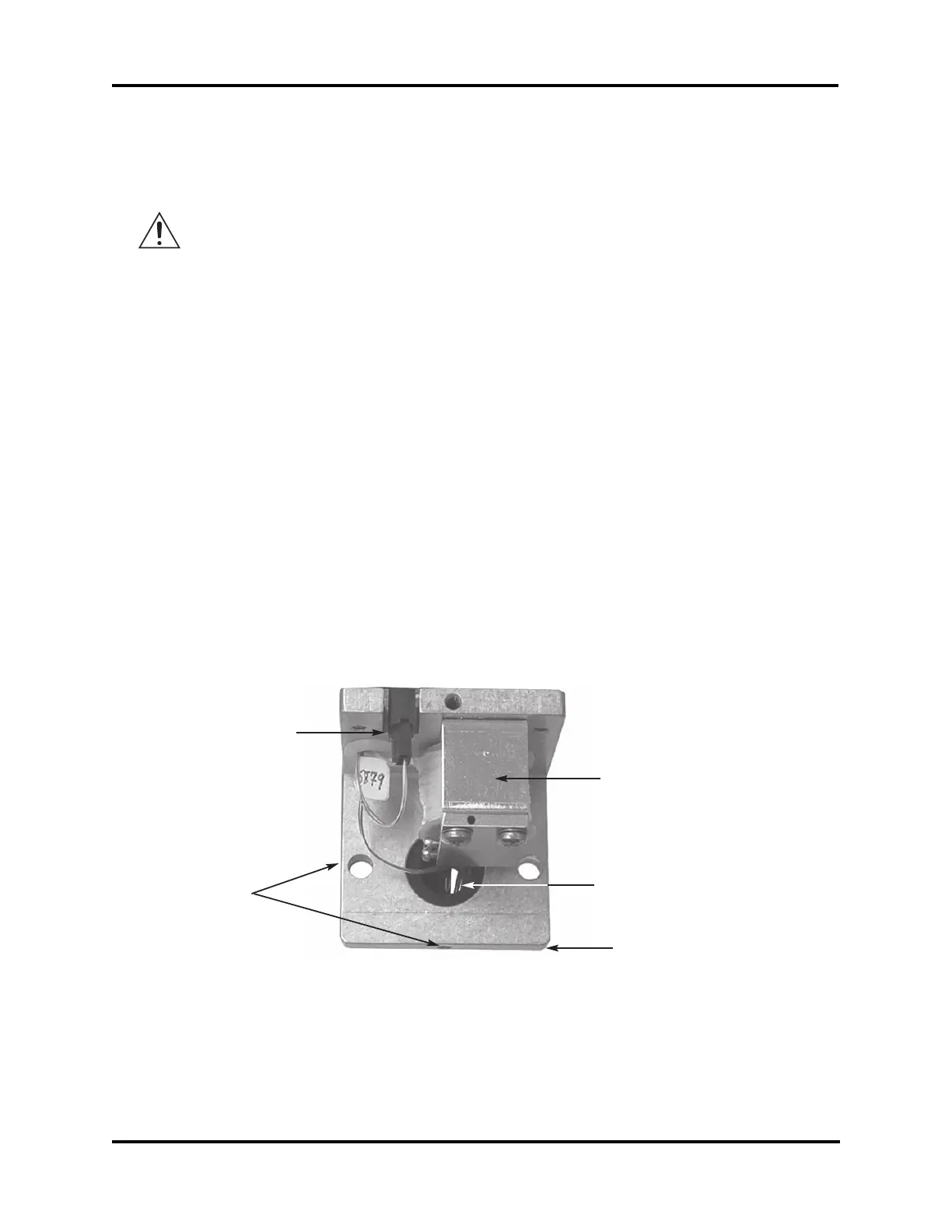
Figure 2. Elevated View of Osmometer Head
Stir Wire Slot in Mandrel
Sample Probe Connector
Mandrel Setscrews
Yoke
Front of Sample Head