3LP700 Rev10
(4C35/4D35/3255/MK05 Service Manual)
Page 3 of 5
gently retighten the probe setscrew
(overtightening will crack or distort
the thin plastic wall of the mandrel).
5. After completing any adjustments,
recheck the probe alignment and level.
6. Check the stir wire alignment and level
(see Figure 3 notes). In the front-to-back
direction, the stir wire should be even
with the sample probe.
7. If necessary, make stir wire adjustments,
as follows:
a. To realign the stir wire in the slot in
the mandrel, note the position of the
top of the yoke relative to the top of
the head, then partially loosen the coil
core/yoke screw (see Figure 4) from
the back of the head. Move the yoke/
clapper/stir wire assembly side-to-side
until the stir wire is in the correct
position relative to the slot. Make
sure to maintain the previously noted
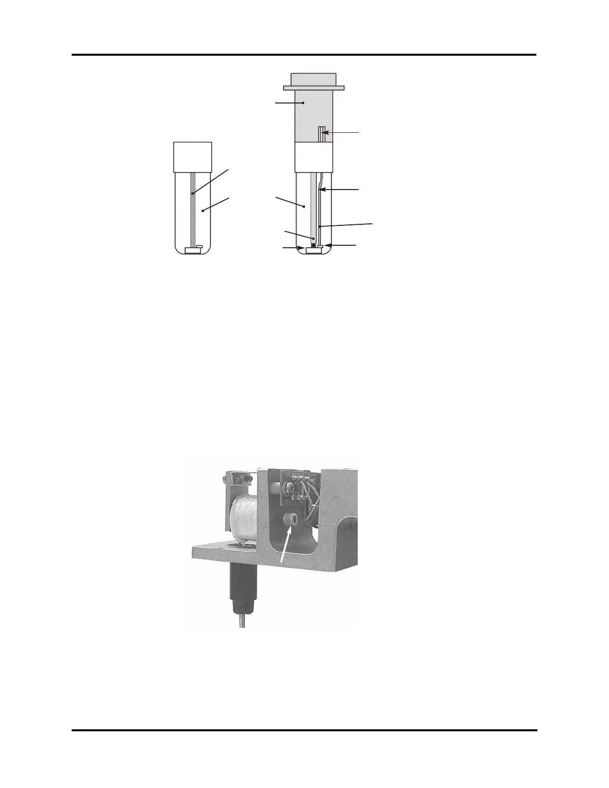
Make sure the stir wire
does not rub on the
sides of the slot in the
mandrel.
This portion of the stir wire should
be parallel to sample probe, and
the space should be about .04
inches (1 mm).
End of stir wire should
rest on this small step.
Bottom of sample probe
should rest on this level.
Mandrel
Raised V
Centerline
Alignment
Tool
Sample Probe
Stir Wire
Figure 3. Osmometer Alignment
Figure 4. Coil Core Mounting Screw