20 Gear Drive, Plymouth Ind. Park, Terryville, CT 06786
Tel: (860) 585-1254 Fax: (860) 584-1973 http://www.amci.com
SMD17E2 User Manual
IMPLICIT COMMUNICATIONS WITH AN EDS
107
3.5 Configure the SMD17E2 Driver
If you are continuing from step 3.4, the resulting New Module screen is used to configure the network con-
nection between the SMD17E2 and your controller. If you need to open the screen to perform this task at a
later time, right click on the SMD17E2 in the project tree and then select “Properties” from the drop-down
menu
Tabs that are not listed in the steps below are filled with reasonable defaults by the EDS file.
3.5.1 General Tab
The Name, Description, and IP address of the device must be specified here. The [Change...] button allows you
to change the Module Definition if needed.
3.5.2 Connection Tab
The default RPI time is eight milliseconds. This value can be changed in this tab.
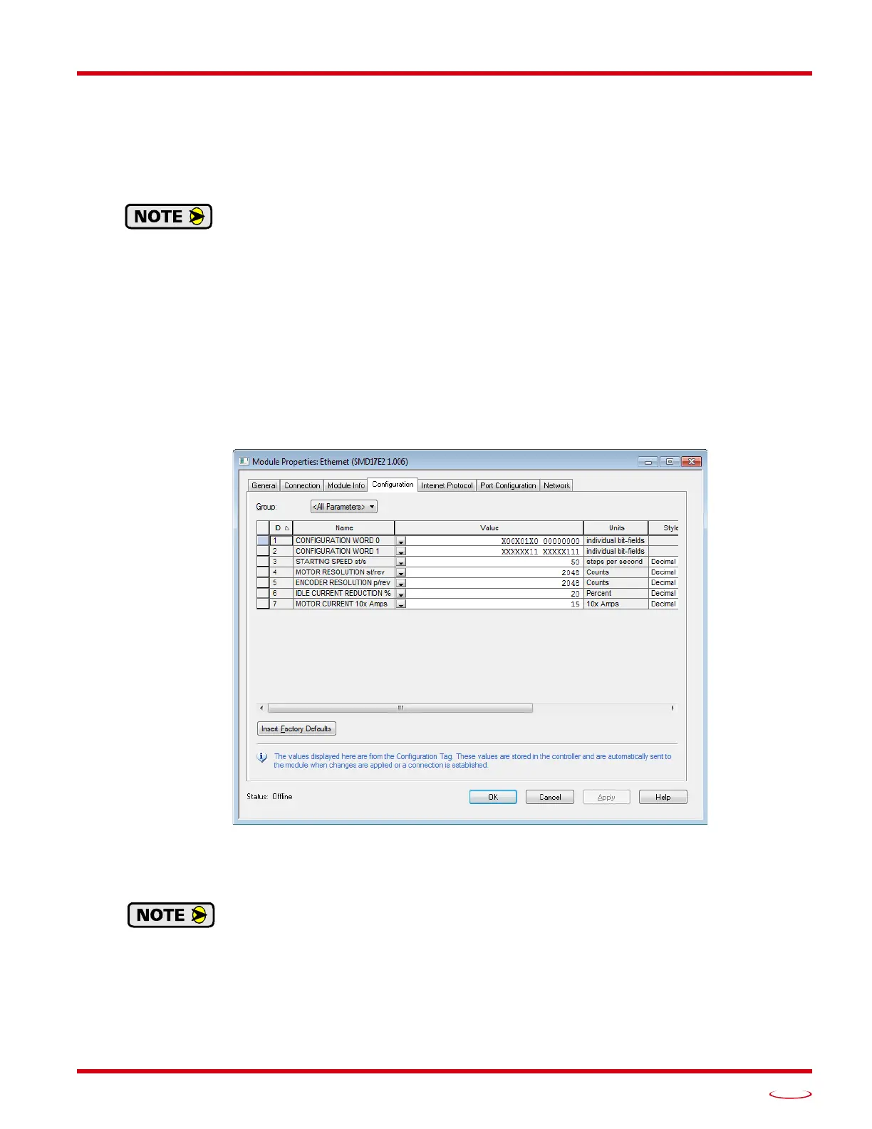
3.5.3 Configuration Tab
The Configuration tab is used to define the configuration data that is written down to the SMD17E2 when the
device connects to the network. You can also click on the [Apply] button to write down the configuration data
to the SMD17E2 at any time.
Figure T3.8 Networked Driver Configuration with EDS File
The EDS file defines tags that are used to configure the SMD17E2. These tags follow the format of the Con-
figuration Data given in reference chapter 6, Configuration Mode Data Format, starting on page 59.
Bits 8 and 9 of Configuration Word 1, Binary_Output_Format and Binary_Input_Format,
should both be set to “1” when using and EDS setup so that command and response data is
sent as 32-bit binary values.