MOTION CONTROL
SMD17E2 User Manual
ADVANCED MICRO CONTROLS INC.
26
Definitions (continued)
Target Position
The Target Position is the position that you want the move to end at. There are two ways to define the Target
Position, with relative coordinates or absolute coordinates.
Relative Coordinates
Relative coordinates define the Target Position as an offset from the present position of the motor. Most
SMD17E2 moves use relative coordinates.
The range of values for the Target Position when it is treated as an offset is ±8,388,607 counts. Positive
offsets will result in clockwise moves, while negative offsets result in counter-clockwise moves.
The Motor Position value reported back to the host exceeds ±8,388,607 counts. If the starting position
or the ending position is outside of the ±8,388,607 count range, relative moves or jog commands must
be used.
Absolute Coordinates
Absolute coordinates treat the Target Position as an actual position on the machine. Note that you must set the
Home Position on the machine before you can run an Absolute Move. (See
Home Position on the previous
page.)
The range of values for the Target Position when it is treated as an actual position on the machine is
±8,388,607 counts. The move will be clockwise if the Target Position is greater than the Current Posi
-
tion and negative if the Target Position is less than the Current Position.
The Motor Position value reported back to the host can ±8,388,607 counts. However, you cannot move
beyond ±8,388,607 counts with an Absolute Move. The only way to move beyond ±8,388,607 counts is
with relative moves or jog commands.
Definition of Acceleration Types
With the exception of Registration Moves, all move commands, including homing commands, allow you to
define the acceleration type used during the move. The SMD17E2 supports three types of accelerations and
decelerations. The type of acceleration used is controlled by the Acceleration Jerk parameter.
Detailed move profile calculations, including the effect of the Acceleration Jerk parameter, can be found in
the reference section,
Calculating Move Profiles, starting on page 43.
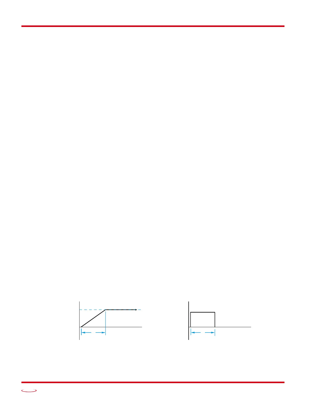
Linear Acceleration
When the Acceleration Jerk parameter equals zero, the axis accelerates (or decelerates) at a constant rate until
the programmed speed is reached. This offers the fastest acceleration, but consideration must be given to
insure the smoothest transition from rest to the acceleration phase of the move. The smoothest transition
occurs when the configured Starting Speed is equal to the square root of the programmed Linear Accelera
-
tion. Note that other values will work correctly, but you may notice a quick change in velocity at the begin-
ning of the acceleration phase.
Figure R2.1 Linear Acceleration
SPEED
ACCELERATION
TIME
t