MODBUS TCP CONFIGURATION
SMD17E2 User Manual
ADVANCED MICRO CONTROLS INC.
120
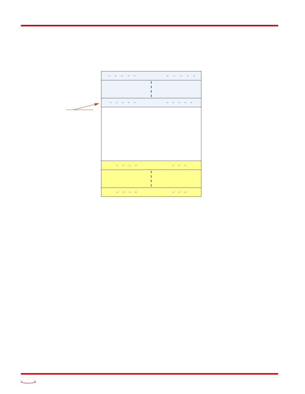
6.3 AMCI Modbus TCP Memory Layout
The SMD17E2 has a starting Input Register address of 0 and a starting Output Register address of 1024.
Input Registers hold the data from the driver while Output Registers hold the data to be written to the unit.
Figure
T6.1 shows how an SMD17E2 is mapped to the Modbus data reference. The complete specification
for the Modbus protocol can be downloaded at http://www.modbus.org/specs.php.
Figure T6.1 Modbus Data Reference Map
Not Implemented
Network Output
Data
LSB and MSB
Numbers
Mapped as:
Discrete Inputs
Holding Registers
Input Registers
Mapped as:
Coils
Holding Registers
Register 1024
Register 1033
16,38416,399
16,52816,543
Register 9
144159
015
Register 0