20 Gear Drive, Plymouth Ind. Park, Terryville, CT 06786
Tel: (860) 585-1254 Fax: (860) 584-1973 http://www.amci.com
SMD17E2 User Manual
CONFIGURATION MODE DATA FORMAT
63
Output Data Format (continued)
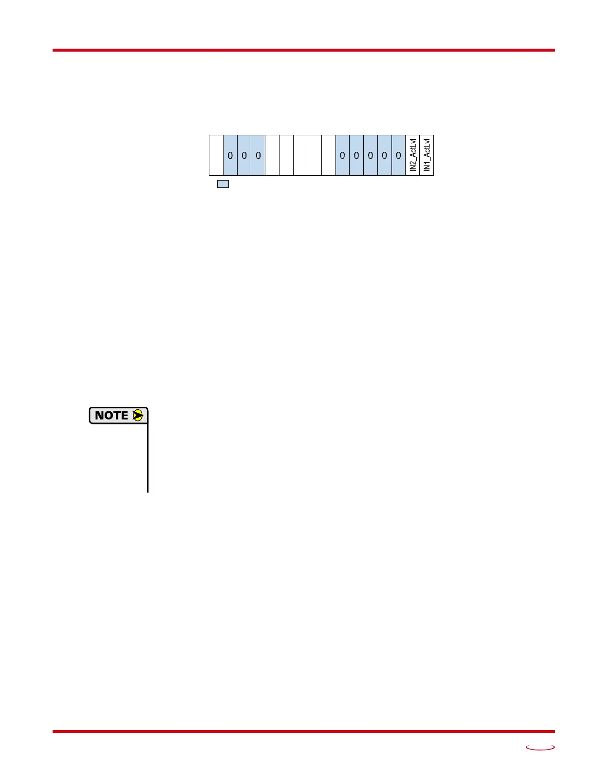
Configuration Word 1 Format
Figure R5.2 Configuration Mode: Config Word Format
Bit 15: Reserved – State ignored.
Bits 14 - 12: Reserved – Must equal zero.
Bit 11: Read_Present_Configuration – If this bit is set when you enter Configuration Mode, the unit
responds by placing the present configuration data in the Network Input Data. You cannot write new
configuration data to the unit while this bit is set. The format of the Configuration Data is given in the
Input Data Format section of this chapter, starting on page 64.
Bit 10: Save_Present_Configuration – An SMD17E2 will store its configuration data to flash memory
when this bit makes a 0
1 transition. The validity of the configuration data is checked before being
written. If the data is not correct, the transition on this bit is ignored. If the write to flash completes
successfully, the unit will write 16#AAAA into the last word of the Network Input Data and the Mod
-
ule Status LED will start flashing green. If the write is unsuccessful, the unit will write 16#EEEE into
the last word of the Network Input Data and the Module Status LED will start flashing red. Once the
unit issues its response to the Save_Present_Configuration command, it stops responding to com
-
mands and you must cycle power to the unit. This design decision prevents the SMD17E2 from
responding to constant save commands from the host controller.
1) This feature was added to support users whose host controllers have very limited function-
ality. Consider the consequences of using this feature. Adding the code necessary to write
down the configuration to an SMD17E2 on power up or network connection is fairly
straight forward on most PLC based hosts. Adding this code allows you to easily change the
configuration in the host and easily configure a new drive if you ever need to swap one out
on the machine.
2) The endurance of the flash memory is a minimum of 10,000 write cycles.
Bit 9: Binary_Input_Format – Set to “0” to have the Motor Position, Encoder Position, and Trapped
Encoder Position reported in the multi-word format. Set to “1” to have the Motor Position, Encoder
Position, and Trapped Encoder Position reported in signed 32-bit integer format. When this parame
-
ter is set to “1”, the Binary_Endian parameter in bit 7 sets the word order of the 32-bit value. See
Position Data Format Examples found on page 60 for examples of the different formats.
Bit 8: Binary_Output_Format –
Set to “0” to program the multi-word parameters in
the multi-word for-
mat.
Set to “1” to program the multi-word parameters in signed 32-bit integer format.
When this
parameter is set to “1”, the Binary_Endian parameter in bit 7 sets the word order of the 32-bit value.
See
Position Data Format Examples
found on page 60
for examples of the different formats.
Bit 7: Binary_Endian –
Only used when bits 8 and/or 9 above are set to “1”, set to “0” to the 32-bit values
in little endian format. Set to “1” to program the 32-bit values in big endian format.
Siemens proces-
sors typically use big endian format, but you should refer to your PLC’s documentation to verify the
format used by your processor.
See Position Data Format Examples
found on page 60
for examples
of the different formats.
Bits 6 - 2: Reserved – Must equal zero.
Configuration Word 1
15 14 13 12 11 10 09 08 07 06 05 04 03 02 01 00
0/1
RESERVED: Bit must equal zero.
ReadConfig
SaveConfig
BinInFrmt
BinOutFrmt
DataEndian